background image

90

Replacing the power supplies


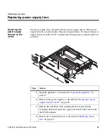
Installing a power 
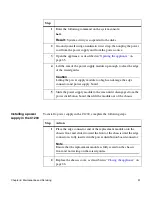
supply in the C2100

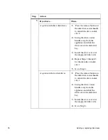
To install a power supply in the C2100, complete the following steps.

.

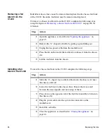
Removing a power 
supply from the 
C1200

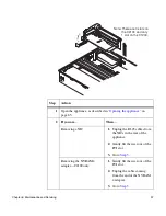
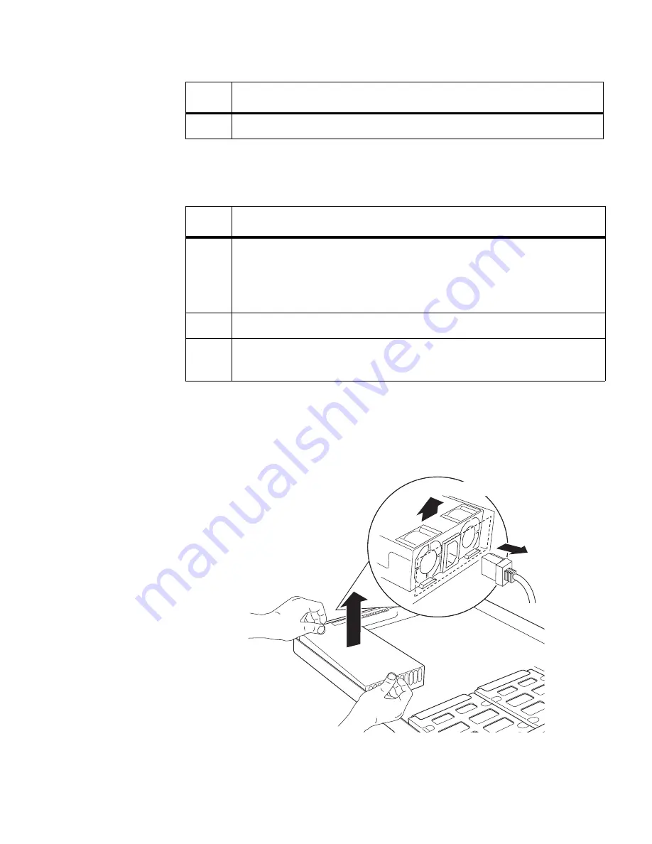
To remove a power supply from the C1200, complete the following steps, using 
the figure for reference

3

Slide the power supply assembly out of the power supply cage.

Step

Action

Step

Action

1

Align the new power supply with the opening in the power supply 
cage, then carefully slide it into the power supply cage. 
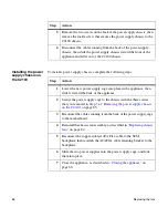
Make sure that the locking latch is in the upper-left corner of the 
power supply.

2

Swing the lock up and push it into the power supply frame.

3

Plug the power cord into the appliance, then back into the power 
source.

View of back

Summary of Contents for C1200 NetCache

Page 1: ...Network Appliance Inc 495 East Java Drive Sunnyvale CA 94089 USA Telephone 1 408 822 6000 Fax 1 408 822 4501 Support telephone 1 888 4 NETAPP Documentation comments doccomments netapp com Information...

Page 2: ...Union Network Appliance is a registered trademark of Network Appliance Inc in Monaco and a trademark of Network Appliance Inc in the United States and Canada FAServer is a registered trademark of Netw...

Page 3: ...Connecting the NetCache appliance 11 Connecting to an Ethernet network 12 Connecting through an RJ45 connection 13 Connecting through a fiber optic GbE network 14 Connecting to an ASCII terminal cons...

Page 4: ...lti disk C1200 75 Downgrading a multi disk C1200 to a single disk C1200 77 Replacing the fans 80 Replacing chassis fans 82 Replacing power supply fans 85 Replacing the CPU heatsink fan 87 Replacing th...

Page 5: ...t the equipment is properly supported or braced when installing options This equipment is designed for connection to a grounded outlet The grounding type plug is an important safety feature To avoid t...

Page 6: ...n Sorgen Sie daf r dass das Ger t richtig abgest tzt ist oder fest aufrecht steht bevor Sie neues Zubeh r einbauen Dieses Ger t ist f r die Einspeisung aus einer geerdeten Netzverbindung ausgelegt Der...

Page 7: ...ork File System NFS Common Internet File System CIFS and Hypertext Transfer Protocol HTTP protocols are used to share and transfer files Terminology This guide uses the following terms FRU refers to a...

Page 8: ...er to the key that generates a carriage return although the key is named Return on some keyboards type Used to mean pressing one or more keys on the keyboard enter Used to mean pressing one or more ke...

Page 9: ...contains instructions that you must follow to avoid damage to the equipment a system crash or loss of data WARNING WARNING A warning contains instructions that you must follow to avoid personal injury...

Page 10: ...x Preface...
Page 11: ...0 NetCache appliance It describes the following Physical characteristics such as height and weight Electrical environmental and space requirements Installation tools and equipment you need Components...

Page 12: ...t The NetCache appliance user guides Equipment rack installation components The following table lists the components you receive to install the NetCache appliance in a specific type of equipment rack...

Page 13: ...stem you need the following equipment on site ASCII terminal also referred to as an ANSI terminal Serial console Communications server Required documentation The following table lists additional docum...

Page 14: ...ents for the appliance Physical characteristics The following table lists the physical characteristics Environmental requirements The following table lists the environmental ranges for operation and s...

Page 15: ...ng at 40 C 90 noncondensing at 35 C Environmental condition Operating range Storage range Recommended minimum clearance U S Metric Front clearance Cooling 1 in 2 54 cm Maintenance without slide rails...

Page 16: ...environmental parameters Note For detailed environmental and electrical information see the Site Requirements Guide Power Rating C1200 C2100 310W 152W Heat dissipation BTU hr C1200 C2100 519 BTU hr ma...

Page 17: ...the types of installations you can perform Double two post installation using slide rails Two post equipment rack as a mid mount or flush mount installation Topics in this chapter This chapter discus...

Page 18: ...ost equipment rack complete the following steps Step Action 1 Unpack the supplied slide rail kit and follow the enclosed instructions to install the slide rails and the appliance into the equipment ra...

Page 19: ...rack using the appropriate screws from the mounting kit Do not tighten the screws completely The bracket should have some play for proper alignment 2 Attach the slide rail to the front most tab on th...

Page 20: ...ur for the C2100 through the holes in the left and right mounting handles and slide rail ears Note After tightening the brackets on your C1200 the chassis might sag slightly To keep the chassis from s...

Page 21: ...es how to connect the NetCache appliance to a network through several types of Ethernet adapters and how to connect the appliance to an ASCII terminal console Topics in this chapter This chapter discu...

Page 22: ...he cabling requirements for the system Ethernet connections For detailed information For detailed information about network connections see the following sections Connecting through an RJ45 connection...

Page 23: ...to a 10Base T 100Base TX or 10Base T 100Base TX 1000Base T Ethernet network complete the following step Step Action 1 Push the RJ 45 connector into the Ethernet port until it clicks and locks into pl...

Page 24: ...bE network Connecting through a fiber optic GbE connection To connect the appliance to a fiber optic GbE network complete the following step Step Action 1 Push the fiber optic cable with the SC connec...

Page 25: ...g The ASCII terminal console is connected to the serial port on the back of the appliance with a serial DB 9 to RJ 45 cable The following table lists how this cable is wired Input indicates data flow...

Page 26: ...he same values for both the appliance and ASCII terminal Parameter Setting Baud 9600 Data bit 8 Parity None Stop bits 1 Flow control None Note See your terminal documentation for information about cha...

Page 27: ...chapter describes how to prepare the NetCache appliance for initial power on and what to expect when you apply power to the appliance Topics in this chapter This chapter discusses the following topics...

Page 28: ...power button on the front of the appliance bezel 4 Observe the messages on the front LCD of the C2100 and on the terminal console of the C1200 during boot If you encounter errors see Startup error mes...

Page 29: ...preconfigured to supply information to your appliance these values might be supplied All you need to do is confirm the displayed values After you bring up the system you need to complete the configur...

Page 30: ...eps using the figure for reference 3 Enter the requested information through the ASCII console keyboard Note If you need to stop the setup program press Ctrl C To restart the setup program enter setup...

Page 31: ...ront of the bezel select the field you want to change 2 Press the Increment or Decrement buttons to change the highlighted value in the display 3 Press Enter to accept the displayed value and to move...

Page 32: ...22 Configuring the appliance at initial boot...

Page 33: ...encounter during the boot process It also describes the location of the LEDs and how to interpret the information they provide Topics in this chapter This chapter discusses the following topics Start...

Page 34: ...ys errors in configuration or hardware as messages on the system console The following list specifies the types of POST error massages you might see Environmental messages displayed as English error m...

Page 35: ...ystem configuration NetApp Release x x x Thu January 10 04 06 00 PST 2002 Copyright c 1992 2002 Network Appliance Inc Starting boot on Thu January 10 23 42 47 GMT 2002 System ID 0016777216 slot 0 Syst...

Page 36: ...e or code Description Corrective action Boot DeviceErr The CompactFlash card could not be found to boot from Insert a CompactFlash card Clock bogus Date reset The system real time clock RTC contains a...

Page 37: ...system LCD device is not operating correctly All subsequent POST messages are displayed on the console C2100 only Replace the motherboard or replace the chassis No power info The system is clearly run...

Page 38: ...in the system either stopped or are running slowly The appliance reached a critical temperature and is too hot A power voltage line is in a critical state and not functioning properly Do one of the fo...

Page 39: ...em memory is different than expected Replace the motherboard as described in Replacing the motherboard on page 102 If the problem persists call Network Appliance Customer Support 11B Date time not set...

Page 40: ...replace the NIC you removed in Step 2 Otherwise repeat Steps 1 and 2 with the remaining NICs and the NVRAM 4 adapter 4 Replace the motherboard as described in Replacing the motherboard on page 102 If...

Page 41: ...st 8150 Processor 1 failed initialization on last boot The CPU did not initialize properly 8160 Processor 01 unable to apply BIOS update The CPU cannot apply a recent BIOS update 8170 Processor P1 L2...

Page 42: ...different 8196 Processor models are different The expected and detected CPU models are different 8197 CPU speed mismatch The expected and detected CPU speeds are different 8300 Baseboard management c...

Page 43: ...e BMC is in update mode and is not operating 84F4 Sensor data record empty The sensor data log is empty 84FF System event log full The system event log is full and did not record properly 1 Ignore thi...

Page 44: ...or system configuration information use the information you recorded in the appliance configuration information worksheet in the Getting Started Guide For more information about the appliance setup pr...

Page 45: ...disk firmware is an old version Update the disk firmware by entering the following command disk_fw_update No disks The system cannot detect any SCSI disks Verify that all disks are properly seated in...

Page 46: ...work Appliance Customer Support for help A disk failed at the same time the system crashed Contact Network Appliance Customer Support to learn how to repair the file system Invalid PCI card slot d d T...

Page 47: ...dapter C2100 only Make sure that the NVRAM adapter is securely installed in riser and is plugged in properly Replace NVRAM batteries The NVRAM battery is low The system shuts down immediately C2100 on...

Page 48: ...ntly monitor heat power and other environment characteristics while the system is operating The following table specifies the sensor names displayed in the error messages Sensor type C2100 sensors C12...

Page 49: ...ply 1 Power Supply 2 N A Sensor type C2100 sensors C1200 sensors Error message Explanation Corrective action Disk n is broken n The RAID group disk number The solution depends on whether you have a ho...

Page 50: ...problem to Network Appliance Customer Support Panicking The system is crashing If the system does not hang while crashing the message Dumping core appears Report the problem to Network Appliance Cust...

Page 51: ...of five system fans are spinning below the critical limit System will be shut down C1200 only Temperature a within normal operating temperature range current reading range A temperature is back to a n...

Page 52: ...ng down the system because of Power a POWER SUPPLY FAILED A power voltage is outside the critical limit The system shuts down Replace the power supply as described in Replacing the power supplies on p...

Page 53: ...OST error message or number A POST error was detected at the POST error sensor See Startup error messages on page 24 for information about the displayed error Critical Interrupt event A bus error was...

Page 54: ...detected at the DIMMn n 1 6 sensor Fault status Installed Disabled Replace the identified DIMM if faulty as described in Replacing the DIMMs in the appliance on page 92 Sensor failure event One of th...

Page 55: ...nd lists the corrective action you need to take Interpreting single beeps The following table lists the single beep error code messages you might encounter provides a brief explanation of what the err...

Page 56: ...memory test failure The error could be one of the following No memory was found in the system Memory mixed type detected EDO is not supported First row memory test failure Mismatched DIMMs in a row Ba...

Page 57: ...apter is either missing or its memory is faulty This is not a fatal error 9 ROM checksum error System BIOS ROM checksum error 10 Shutdown register error Shutdown CMOS register read write error detecte...

Page 58: ...t the LEDs see the following sections External LEDs on page 49 Internal LEDs on page 60 LED location Basic information given External LEDs LEDs visible on the front of the appliance with the bezel in...

Page 59: ...D Network 1 Network 2 LED Status indicator Description Activity Green blinking The system is actively processing data Off No activity is detected Status Green The system is operating normally Amber Th...

Page 60: ...scription NIC network connectivity Green The appliance is connected to the network Off There is no network connection present NIC network communication Blinking amber Data is being transmitted across...

Page 61: ...tus Power Status LCD LED label Status indicator Description Activity Green The system is operating and is active Blinking The system is actively processing data Off No activity is detected Status Gree...

Page 62: ...for the motherboard LEDs is a two step procedure listed in the following table Optional NICS On board Ethernet adapters AC power LEDs AC power ports LED type Status indicator Description NIC network...

Page 63: ...require replacing the motherboard Follow the instructions the Customer Support representative gives you Requires replacing the motherboard Replace the motherboard as described in Replacing the motherb...

Page 64: ...ization after the keyboard controller BAT command test 0Fh Grn Grn Grn Grn Write Command Byte 8042 The initialization after the keyboard controller BAT command test is done The keyboard command byte i...

Page 65: ...r Initialize USB emulation F5h Red Amb Red Amb Validate NVRAM areas Restore from backup if corrupted 12h Off Off Grn Red Load defaults in CMOS RAM if bad checksum or CMOS clear jumper is detected Init...

Page 66: ...sage next Initialize language module Display splash logo Display sign on message BIOS ID and processor information 38h Grn Off Red Red Detect USB mouse Initializing the bus input and general devices n...

Page 67: ...Grn Amb Amb Amb Extended NMI Enable Extended NMI source enabling is in progress 80h Red Off Off Off Enable Mouse and Keyboard The keyboard test started Clearing the output buffer and checking for stuc...

Page 68: ...D Devices Resetting the hard disk controller next 95h Red Grn Off Amb Lock out PS 2 keyboard mouse if unattended start is enabled 92h Red Off Grn Red Option ROM scan 98h Amb Off Off Red Init Boot Devi...

Page 69: ...A5h Red Grn Red Grn Set display mode A7h Red Grn Amb Grn OEM patch 12 Build SMBIOS table and MP tables Program hot key and timeout settings in keyboard controller Processor initialization before boot...

Page 70: ...owing figure and table show and describe the disk drive LED that is visible after you remove the bezel Indicator type Status indicator Description Disk drive LED Blinking green Data is being accessed...

Page 71: ...pter discusses the following topics Field replaceable unit overview on page 62 Required tools and equipment on page 64 Opening the appliance on page 65 Closing the appliance on page 66 Adding or repla...

Page 72: ...the C1200 and C2100 C1200 C2100 Appliance base or chassis with motherboard N A N A Motherboard Cold swap disk drives 36 GB disk drive with the drive carrier 72 GB disk drive with the drive carrier Hot...

Page 73: ...component that is not on the FRU list you must call Network Appliance Customer Support for instructions Expansion adapters N A GbE network adapter 10Base T 100Base TX 1000Base T GbE network adapter Ex...

Page 74: ...ag Caution The appliance uses electronic components that are sensitive to static electricity Static discharge from your clothing or other fixtures around you can damage these components Wear an antist...

Page 75: ...ance and disconnect it from all power sources Note Because of the weight of the C2100 you should remove the power supplies before removing the appliance from the equipment rack See Removing a power su...

Page 76: ...slide the cover down and forward to seat it 2 Reinstall the appliance into the rack as described in Installing the NetCache appliance on page 7 Note If you have a C2100 and removed the power supplies...

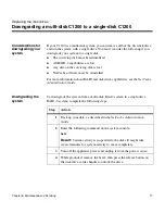
Page 77: ...depending on how many disk drives your system has If your C1200 system has two or more disk drives they are replaced or installed the same way as a C2100 system However if your C1200 has only one dis...

Page 78: ...Removing a disk drive on page 68 Installing a disk drive on page 69 Removing a disk drive To remove a disk drive from the C2100 complete the following steps using the figure for reference Step Action...

Page 79: ...to Installing a disk drive on page 69 Not installing or replacing a disk drive Install the slot cover over the empty slot Step Action Step Action 1 Remove the slot cover if applicable then align the r...

Page 80: ...without shutting down the system If you are replacing a disk in a single disk system the system must be shut down and the replacement process must be treated as if the C1200 system were being install...

Page 81: ...n on the disk drive carrier handle to unlock the drive 5 Swing the drive carrier handle away from the appliance and slide the drive out of the disk drive bay Step Action 1 Make sure that the system is...

Page 82: ...C for special boot menu 5 Press Ctrl C on your keyboard and select 4 from the following menu Result The console displays the following menu 1 Normal Boot 2 Boot without starting system devices 3 Chang...

Page 83: ...to place Make sure that the drive is secure by giving it a gentle tug If the drive comes out reseat it and lock it into place then replace the bezel 7 Repeat Steps 4 through 6 for drive slot 2 if you...

Page 84: ...the data on the disks are you sure 11 Reserve a disk as a hot spare by entering Y to the following question Reserve a disk for use as a hot spare Result Disk 0 is reserved as a hot spare You see the...

Page 85: ...e following steps Step Action 1 Enter the following command on the system console disk swap Result System activity is suspended to the disks allowing you to safely remove the disk See the NetCache Adm...

Page 86: ...the way into the bay Note If you are adding a third disk to a two disk system you might need to remove the slot cover from disk slot 2 Remember to save the slot cover for later use 2 Close the drive c...

Page 87: ...be reinstalled For more information about RAID and disk drive capabilities see the NetCache Administration Guide Downgrading the system To downgrade the system from a multi disk Raid 4 system to a si...

Page 88: ...f the disk drive bay 3 Install the slot cover over the empty disk drive slot 4 Repeat Steps 1 through 3 for the disk drive in disk slot 1 5 Go to Step 6 A system with two disk drives 1 Press the relea...

Page 89: ...ss Ctrl C on your keyboard and select 4 from the following menu Result The console displays the following menu 1 Normal Boot 2 Boot without starting system devices 3 Change Password 4 Initialize all d...

Page 90: ...e power supply fan or CPU heatsink fan fails therefore requiring immediate replacement Procedures for replacing fans Replacing a chassis fan consists of the following procedures Removing a chassis fan...

Page 91: ...ssis on the C2100 on page 85 Installing the power supply chassis on the C2100 on page 86 Replacing the CPU heatsink fan consists of the following procedures Removing the CPU heatsink fan from the C210...

Page 92: ...from the chassis fan block in the C2100 To remove a chassis fan from the fan block complete the following steps using the figure for reference for both the C2100 and C1200 Step Action 1 Open the appl...

Page 93: ...an block Step Action Step Action 1 Insert the fan into the open slot in the fan block pushing the fan from the bottom so it snaps into place Note Ensure that the fan is inserted into the fan block so...

Page 94: ...ppliance on page 65 2 Remove the L shaped air baffle by pulling up and lifting out 3 Unplug the fan power cable from the motherboard 4 Press the tab on the end of the fan block to release it from the...

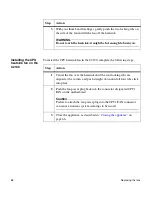
Page 95: ...upply chassis from the C2100 complete the following steps using the figure for reference Step Action 1 Open the appliance as described in Opening the appliance on page 65 2 Remove both power supplies...

Page 96: ...r supply cage into place in the appliance then slide it toward the back of the appliance 2 Secure the power supply cage to the chassis with the three screws that you removed in Step 5 of Removing the...

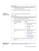
Page 97: ...PU heatsink fan from the C2100 To remove the CPU heatsink fan from the C2100 complete the following steps using the figure for reference Step Action 1 Open the appliance as described in Opening the ap...

Page 98: ...eatsink it might be hot enough to burn you Step Action Step Action 1 Center the fan over the heatsink until the four locking tabs are aligned at the corners and push straight down until all four tabs...

Page 99: ...ng a power supply consists of the following procedures Removing a power supply from the C2100 on page 89 Installing a power supply in the C2100 on page 90 Removing a power supply from the C1200 on pag...

Page 100: ...figure for reference 3 Slide the power supply assembly out of the power supply cage Step Action Step Action 1 Align the new power supply with the opening in the power supply cage then carefully slide...

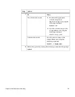
Page 101: ...enough to clear the edge of the raised guides Caution Lifting the power supply module too high can damage the edge connector and power supply board 5 Slide the power supply module to the rear until it...

Page 102: ...tion All DIMMS must be listed on the Network Appliance Approved Parts List Contact Network Appliance Sales to obtain this list Unapproved DIMMs have not been tested for reliability and might cause sys...

Page 103: ...he DIMM socket until the DIMM pops free of the socket then lift the DIMM free Step Action 1 Align the new DIMM with the socket making sure that the notches at the end of the DIMM are aligned with the...

Page 104: ...acing the DIMMs in the appliance 2 Press down on the DIMM while pulling up on the ejectors to lock the DIMM into the socket 3 Close the appliance as described in Closing the appliance on page 66 Step...

Page 105: ...s occur The battery continues to read low after 24 hours of normal system operation The system does not boot or you receive warning messages during boot that the CompactFlash card is invalid or damage...

Page 106: ...tem Configuration Guide or install it in an expansion slot not listed in the guide Installing an expansion adapter incorrectly or using an unsupported adapter can adversely affect your system performa...

Page 107: ...1 Unplug the RJ 45 cables from the NICs in the rear of the appliance 2 Gently lift the riser out of the PCI slot 3 Go to Step 3 Removing the NVRAM 4 adapter C2100 only 1 Gently lift the riser out of t...

Page 108: ...from the riser assembly Step Action Step Action 1 Install the adapter into the riser assembly making sure that you do not flex or bend the adapter while installing it 2 Swing the locking clip back in...

Page 109: ...es After POST is completed the console displays the following menu Data ONTAP backup Data ONTAP Service Menu 2 Using the arrow keys select Service Menu from the list Result The appliance console displ...

Page 110: ...An error message appears stating that it cannot boot from the selected disk 1 Press any key to return to the Disk boot menu and select one of the following boot options Boot from the second disk if p...

Page 111: ...ing the following command install dl 2 Save the software image to the CompactFlash card using the following command install c image_name Software files match Save the software image to the CompactFlas...

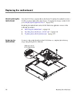
Page 112: ...o Replacing the appliance chassis on page 106 Replacing the motherboard on the C2100 NetCache appliance consists of the following procedures Removing the motherboard on page 102 Installing the motherb...

Page 113: ...les with small plugs Note For later reference during reinstallation record the routing location and direction of each of the cables as you unplug and remove them 4 Remove the ATA Flex cable retaining...

Page 114: ...the expansion adapter ID ports 3 Plug all power wires and the SCSI ribbon cable into the motherboard Caution Make sure that you match the wires with the correct plugs on the motherboard and have atta...

Page 115: ...Service Menu from the list Result The appliance console displays service and boot options 3 Select Platform Specific Services from the list Result Several platforms are displayed including the applian...

Page 116: ...mplete the following steps Step Action 1 Ground yourself then remove the cover and bezel of the appliance as described in Opening the appliance on page 65 2 Remove the disk drives as described in Addi...

Page 117: ...iance with the chassis C2100 Remove the motherboard as described in Removing the motherboard on page 102 7 Go to Installing the chassis on page 107 Step Action Step Action 1 If you have a Then C1200 Y...

Page 118: ...install the chassis back into the equipment rack as described in the appropriate section of Installing the NetCache appliance on page 7 6 Install the disk drives as described in Adding or replacing di...

Page 119: ...Appendix A Recommended Power Line Size 109 A Recommended Power Line Size About this appendix This appendix discusses how to determine the power line requirements...

Page 120: ...s the recommended conductor size for a 2 voltage drop for a particular distance in feet taken from the Radio Engineer s Handbook Wire gauge approximates The following table lists the approximate equiv...

Page 121: ...Communications Regulations 111 B Communications Regulations About this appendix This appendix lists the regulatory notices you need to be aware of when installing and operating your Network Appliance...

Page 122: ...ance with Part 15 of CFR 47 This equipment has been tested and found compliant with Part 15 of the CFR 47 rules for Class A digital devices These rules are designed to provide reasonable protection fr...

Page 123: ...mestic environment this product may cause radio interference in which case the user may be required to take adequate measures Voluntary Control Council for Interference by Information Technology Equip...

Page 124: ...y of Laser LED Equipment IEC 1000 3 2 1995 Limits for Harmonic Current Emissions IEC 1000 3 3 1994 Limitation of Voltage Fluctuations and Flicker in Low Voltage Supply Systems following the provisions...

Page 125: ...Halted firmware too old 35 Halted illegal configuration 35 Invalid PCI card slot d 36 No etc rc 34 No etc rc running setup 34 No disks 35 No network interfaces 37 No NVRAM present 37 NVRAM n downrev...

Page 126: ...18 flush mount in a two post rack 9 in a double two post equipment rack 8 mid mount in a two post rack 9 POST messages 24 required manuals 3 startup sequence 24 L LEDs disk drive 60 during power on 1...

Page 127: ...or codes additional 100 28 101 28 102 28 103 28 104 29 105 29 106 29 107 29 108 29 109 29 10A 29 10B 29 11B 29 11E 29 120 30 121 30 140 30 141 30 142 30 143 30 144 30 145 30 146 30 POST error messages...

Page 128: ...4FF 33 power supplies installing 90 91 LEDs 50 removing 89 90 R racks double two post 8 two post flush mount 9 two post mid mount 9 removing 96 requirements electrical 5 environmental 4 physical 4 spa...

Reviews: