


Chapter 3: Monitoring Your System
61
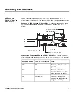
Monitoring the CPU module
LEDs on the
FAS270/FAS270c
CPU module
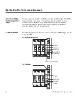
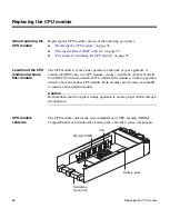
The CPU module has several LEDs. The LEDs indicate whether the CPU
module, Fibre Channel ports, and network connections are functioning normally.
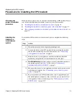
Location of LEDs on the CPU module:
The following illustration shows
the location of the Ethernet and Fibre Channel LEDs at the rear of the CPU
module.
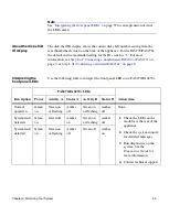
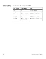
Interpreting Ethernet LEDs on a FAS270/FAS270c:
Use the following
table to interpret the Ethernet port LEDs on the FAS270/FAS270c CPU module.
Link LED (green)
Activity LED (amber)
State
Off
Off
Network connection is not
present.
On
Off
Network connection is
present but there is no data
input or output occurring.
On
On/blinking
Network connection is
present and data input and
output is occurring.
1
Fibre Channel C LED
Fault LED
Fibre Channel B LED
Activity LED (amber)
Link LED (green)
Summary of Contents for FAS200 Series
Page 4: ...iv Copyright and trademark information...
Page 10: ...x Preface...
Page 76: ...64 Monitoring the CPU module...
Page 126: ...114 Troubleshooting hardware problems...
Page 134: ...122 Feature Update Record...


