background image

102

Environmental EMS messages


Environmental EMS messages

Environmental EMS 
messages

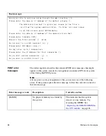
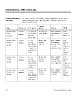
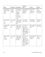
The following table describes the environmental EMS messages that might 
appear on the system console if your appliance encounters extremes in its 
operational environment.

Name

Parameters

Description

Corrective 
action

Syslog

SNMP

monitor.chassis
Fan.ok

NOTICE

fru_name

STRING

This message 
is issued when 
the chassis 
fans are OK.

No corrective 
action needed.

LOG_NOTICE: 
Chassis FRU is 
ok

#366: 
Chassis 
FRU is ok

monitor.chassis
Fan.slow

ALERT

fru_name

STRING

This is a 
warning 
message that 
is issued when 
a chassis fan 
is spinning too 
slowly.

The fan unit 
should be 
replaced.

LOG_ALERT: 
Chassis FRU 
contains at least 
one fan 
spinning slowly

#365: 
Chassis 
FRU 
contains at 
least one 
fan 
spinning 
slowly

monitor.chassis
Fan.stop

ALERT

fru_name

STRING

This is a 
warning 
message that 
is issued when 
a chassis fan 
is stopped.

The fan unit 
should be 
replaced.

LOG_ALERT: 
Chassis FRU 
contains at least 
one stopped fan

#364: 
Chassis 
FRU 
contains at 
least one 
stopped fan

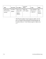
monitor.chassis
Fan.removed

ALERT

fan_name

STRING

This is a 
warning 
message that 
is issued when 
a chassis fan 
is removed.

The fan unit 
should be 
replaced.

LOG_ALERT: 
Chassis FRU is 
removed

#363: 
Chassis 
FRU is 
removed

Summary of Contents for FAS200 Series

Page 1: ...Network Appliance Inc 495 East Java Drive Sunnyvale CA 94089 USA Telephone 1 408 822 6000 Fax 1 408 822 4501 Support telephone 1 888 4 NETAPP Documentation comments doccomments netapp com Information...

Page 2: ...stered trademarks of Network Appliance Inc in the U S A and or other countries Cryptainer Cryptoshred Datafort and Decru are registered trademarks and Lifetime Key Management and OpenKey are trademark...

Page 3: ...Copyright and trademark information iii Network Appliance is a licensee of the CompactFlash and CF Logo trademarks Network Appliance NetCache is certified RealSystem compatible...

Page 4: ...iv Copyright and trademark information...

Page 5: ...6 Connecting to third party devices 27 Connecting to a third party tape backup device 28 Connecting to a third party Fibre Channel switch 30 Connecting your appliance to an ASCII terminal console 32 C...

Page 6: ...le 86 Replacing a power supply 89 Replacing LRC modules with ESH2 modules in a disk shelf 92 Chapter 5 Error Messages and Troubleshooting 95 Startup error messages 96 Environmental EMS messages 102 Ne...

Page 7: ...e carrier Disk shelf refers to any Fibre Channel disk shelf model DS14mk2 refers to both the DS14mk2 FC and the DS14mk2 AT disk shelves unless called out separately ESH Embedded Switching Hub module r...

Page 8: ...tion switch replaces the Output terminators and the auto termination mechanism in previous versions of Fibre Channel disk shelves Command conventions You can enter commands on the system console or fr...

Page 9: ...NG A warning contains instructions that you must follow to avoid personal injury Bold monospaced font Words or characters you type What you type is always shown in lowercase letters unless your progra...

Page 10: ...x Preface...

Page 11: ...and the two input power terminals for the DC power supply must be connected to separate isolated branch circuits To reduce the risk of personal injury or equipment damage allow internal components ti...

Page 12: ...liert sein und die beiden Eingangsstromklemmen f r das Gleichstrom Netzteil m ssen an separate und isolierte Abzweigleitungen angeschlossen sein Zum Schutz vor K rperverletzung oder Sachsch den am Ger...

Page 13: ...ter describes how to connect a FAS250 FAS270 and FAS270c Topics in this chapter This chapter describes the following topics Connecting your appliance to a network on page 2 Connecting additional disk...

Page 14: ...etwork About this procedure You connect your appliance in either a nonclustered configuration FAS250 or FAS270 or clustered configuration FAS270c This chapter describes the following topics Connecting...

Page 15: ...te the following steps Step Action 1 Put on the antistatic wrist strap and grounding leash 2 Make sure that the appliance is turned off 3 Connect your appliance to the network by plugging the network...

Page 16: ...ASCII terminal console on page 32 For FAS270 non RoHS For FAS250 non RoHS Note The Reduction of Hazardous Substances RoHS version of the FAS200 series uses a Small Form Factor Pluggable SFP module in...

Page 17: ...r or loopback terminator into the Fibre Channel port at the far left Port C of the CPU module You are attaching a third party device such as a tape backup or a Fibre Channel switch Plug in the SFP mod...

Page 18: ...t the terminate switch on the CPU module to Off Not connecting your FAS270 to an additional disk shelf Set the terminate switch to On Using a FAS250 system Skip this step and go to Step 8 Non RoHS por...

Page 19: ...1 Attention Power to the appliance must be off before changing the thumbwheel switch value The change takes effect after power is restored to the appliance Do not change the thumbwheel switch ID valu...

Page 20: ...ur clustered FAS270c complete the following steps Step Action 1 Put on the antistatic wrist strap and grounding leash 2 Make sure that the appliance is turned off 3 Connect your appliance to the netwo...

Page 21: ...t before to cabling or terminating it 5 If Then You are not attaching a third party device to the Fibre Channel port Plug in the SFP module if needed and then insert the Fibre Channel terminator into...

Page 22: ...r FAS270 to one or more additional disk shelves Set the terminate switch on the CPU module to Off Not connecting your FAS270 to an additional disk shelf Set the terminate switch to On Non RoHS port la...

Page 23: ...D switch is 1 Attention Power to the appliance must be off before changing the thumbwheel switch value The change will take effect after power is restored to the appliance Do not change the thumbwheel...

Page 24: ...o connect your nonclustered or clustered system to one or more additional DS14mk2 FC or DS14mk2 AT disk shelves For detailed information For details about connecting a disk shelf to a FAS270 FAS270c s...

Page 25: ...on the antistatic wrist strap and grounding leash and then turn off the system Note You can hot add a disk shelf to your system See the DiskShelf14 DiskShelf14mk2 FC and DiskShelf14mk4 FC Hardware and...

Page 26: ...the cable connection on the disk shelf is tight Caution Do not use ESH modules in place of LRC or ESH2 modules The FAS270 FAS270c cannot use ESH modules 4 Attach the grounding cable between shelves as...

Page 27: ...H2 modules is set on the disk shelf AT FCX modules require you to set the loop speed by moving the jumper inside the module LRC and ESH modules do not have a loop speed switch See the DiskShelf14mk2 A...

Page 28: ...m to a power source on page 26 This is the only disk shelf you are adding to your system and your system uses ESH2 or AT FCX modules Proceed to Connecting your system to a power source on page 26 You...

Page 29: ...sure that the cable connections on both disk shelves are tight 8 Attach the grounding cable between shelves as shown in the illustration 9 Set the disk shelf ID on your third disk shelf to 3 and set t...

Page 30: ...terminate switch on the third disk shelf to On and power on your disk shelf and system See Connecting your system to a power source on page 26 Your system uses ESH2 or AT FCX modules Power on your dis...

Page 31: ...system To connect additional disk shelves to your clustered FAS270c complete the following steps Node B Terminate switch Terminate switch Node A Step Action 1 Put on the antistatic wrist strap and gr...

Page 32: ...the rear of your FAS270c confirm that the terminate switches on both CPU modules are set to Off Confirm that the FAS270c shelf ID is set to 1 Step Action 1 1Gb ON OFF 2Gb ON OFF Shelf ID Terminate swi...

Page 33: ...odule Input port of the same disk shelf Make sure that the cables on the disk shelf are tight Do not use ESH modules in place of LRC or ESH2 modules The FAS270 FAS270c cannot use ESH modules 5 Attach...

Page 34: ...modules is set on the disk shelf AT FCX modules require you to set the loop speed by moving the jumper inside the module LRC and ESH modules do not have a loop speed switch See the DiskShelf14mk2 AT H...

Page 35: ...RC modules to On and go to Step 12 This is the only disk shelf you are adding to your system and your system uses ESH 2 modules Go to Step 12 You are adding another disk shelf to a system using LRC mo...

Page 36: ...ESH2 A or AT FCX A module Input port of your third disk shelf Make sure that the cable connections on both disk shelves are tight 9 Attach the grounding cable between shelves as shown in the illustra...

Page 37: ...hapter 1 Connecting a FAS200 Series Appliance 25 11 Set the terminate switch on the third disk shelf to On if applicable 12 Give back the target node and reboot it Run Diagnostics as needed Step Actio...

Page 38: ...ug the power cord for PSU1 into the power receptacle on the left connector rear view 3 Plug the power cord for PSU2 into the power receptacle on the right connector rear view 4 Fasten the power cords...

Page 39: ...compliant systems or copper HSSDC cables for non RoHS compliant systems Rules for connecting third party devices Observe the following rules for connecting third party devices Use the supplied SFP mo...

Page 40: ...nnecting a tape backup device The Fibre Channel interface is hot pluggable meaning that you do not need to power off your appliance before adding the tape backup device To connect a third party tape b...

Page 41: ...ct one end of the copper grounding cable to the threaded hole adjacent to the power supply receptacle on your appliance as shown in the preceding illustration Connect the other end of the grounding ca...

Page 42: ...re Channel switch complete the following steps Step Action 1 Shut down the appliance by entering the following command at the console halt Caution Always use the halt command to perform a clean shutdo...

Page 43: ...ect the cable to the following points of connection The Fibre Channel port on the CPU module at the back panel of your appliance An available port on the Fibre Channel switch For FAS270 FAS270c For FA...

Page 44: ...the appliance ASCII terminal console wiring The following table lists the RJ 45 connection pinout for the ASCII terminal console wiring DB 9 to RJ 45 console adapter pin connections You use the DB 9...

Page 45: ...nects to RJ 45 Pin number Signal Pin number Signal 1 Not connected 1 Not connected 4 Not connected 2 Not connected 3 TXD 3 TXD 5 GND 4 GND 6 Not connected 5 Not connected 2 RXD 6 RXD 7 Not connected 7...

Page 46: ...parameters to the same values for both the appliance and ASCII terminal Parameter Setting Baud 9600 Data bit 8 Parity None Stop bits 1 Flow control None Note See your terminal documentation for infor...

Page 47: ...guring a FAS270 FAS270c About this chapter This chapter describes how to configure a FAS270 FAS270c Topics in this chapter This chapter describes the following topics Configuring for a cluster on page...

Page 48: ...clude planning worksheets and installation procedures for the following tasks Gathering and recording information about the two nodes in System setup information worksheet on page 37 Recording or assi...

Page 49: ...ss second interface e0b Netmask first interface e0a Netmask second interface e0b Media type speed 100tx fd 100tx auto 100 1000 first interface e0a Media type speed 100tx fd 100tx auto 100 1000 second...

Page 50: ...ion each node has ownership of one parity disk and one spare disk Node B owns disks 0b 16 0b 18 and 0b 20 and Node A owns disks 0b 17 0b 19 and 0b 21 The balance of the disks are unowned If you add st...

Page 51: ...ill assign disks to nodes with new systems and if your system has no Fibre Channel disks bays 0 and 1 must contain power supply load boards along with blanks in the remaining drive bays 0 Disk 0b 29 T...

Page 52: ...nership during the setup process Bay Disk shelf 1 Disk shelf 2 Disk shelf 3 Disk ID Node A Node B Disk ID Node A Node B Disk ID Node A Node B 0 0b 16 SES disk 0b 32 SES disk 0b 48 SES disk 1 0b 17 SES...

Page 53: ...plete the disk ownership worksheet as described in Disk reservation and ownership in a FAS270c running Data ONTAP 6 5 0 or earlier on page 38 3 Check that the disk shelf IDs and terminate switches are...

Page 54: ...estion you can press Enter to accept the default setting if you do not know how to set the timezone You can then set the timezone after you complete initial setup See the Timezone manual man page for...

Page 55: ...s the license code for the product a Check the licenses on the node using the license command b Add any missing licenses using the license add command 8 Reboot the node by entering the following comma...

Page 56: ...ing the following command cf giveback d Check the status of the cluster using the cf status command Test takeover and giveback on this node by completing the following steps a Initiate takeover by ent...

Page 57: ...cluster with FCP Complete the following steps a License FCP services b Reboot the appliance this allows the FC port to operate in target mode c Set up LUNs as described in the Data ONTAP Block Access...

Page 58: ...se command for clustered failover Please enter the IP address or interface name to be taken over by e0a 172 22 6 164 Please enter the media type for e0a 100tx fd tp fd 100tx tp auto 10 100 1000 auto P...

Page 59: ...ill send event messages and weekly reports to NetApp Technical Support To disable this feature enter options autosupport support enable off within 24 hours Enabling Autosupport can significantly speed...

Page 60: ...xed initiator target mode The default mode for port 0c is initiator mode If you have not licensed the FCP service and you want to use port 0c in initiator mode you do not need to configure the port No...

Page 61: ...e FCP_code is the FCP service license code provided to you by NetApp Example fas270a license add XXXXXXX A fcp site license has been installed cf takeover on_panic is changed to on Run fcp start to st...

Page 62: ...Host Adapter 0b 14 Disks 952 0GB 1 shelf with EFH slot 0 Fibre Channel Target Host Adapter 0c slot 0 SB1250 Gigabit Dual Ethernet Controller e0a MAC Address 00 a0 98 01 29 cd 100tx fd up e0b MAC Addr...

Page 63: ...ntering the following command license delete fcp Example fas270a license delete fcp Fri Dec 5 14 59 02 EST fas270a fcp service shutdown info FCP service shutdown cf takeover on_panic is changed to off...

Page 64: ...as270b System Serial Number 379589 fas270a slot 0 System Board Processors 2 Processor revision B2 Processor type 1250 Memory Size 1022 MB slot 0 FC Host Adapter 0b 14 Disks 952 0GB 1 shelf with EFH sl...

Page 65: ...n of the various LEDs on your appliance Note The quick reference card in the slide out tray at the base of your appliance describes the functions of each LED on your appliance and the suggested course...

Page 66: ...whether there are problems with the hardware You can also identify any hardware failure associated with the front operation panel of the appliance from the error messages displayed on your system cons...

Page 67: ...ered FAS270c on page 8 Interpreting the front panel LEDs Use the following table to interpret the front panel LEDs on a FAS270 FAS270c Description FAS270 FAS270c LEDs Action item Power Activity A Stat...

Page 68: ...tatus Normal operation Green on Green on or flashing Amber off None System fault detected Green on Green on or flashing Amber on 1 Check the LEDs on the modules at the rear of the appliance 2 Check th...

Page 69: ...ies from the error messages displayed on your system console A normal functioning power supply shows the check mark green LED on the far left as on with the rest of the amber LEDs off A power supply f...

Page 70: ...o interpret the power supply LEDs Fault condition Description LEDs PSU status normal AC missing for this PSU Fan fault Output voltage current temperature fault N Normal operation On Off Off Off 1 Powe...

Page 71: ...the Fibre Channel disk The FAS200 series Fibre Channel disk has two LEDs The LEDs indicate whether the disk is functioning normally or whether there are problems with the hardware Location of LEDs Th...

Page 72: ...t the disk LEDs LED 1 green LED 2 amber State Off Off No drive installed On Blink off Off Drive installed and operational On Flashes 1 second on and 1 second off SES device identification set On or of...

Page 73: ...rnet and Fibre Channel LEDs at the rear of the CPU module Interpreting Ethernet LEDs on a FAS270 FAS270c Use the following table to interpret the Ethernet port LEDs on the FAS270 FAS270c CPU module Li...

Page 74: ...resolved 1 Check the cables at the rear of the system 2 Make sure that the 1 Gb 2 Gb switches are set to 1 Gb 3 Check all terminate switches Last shelf in the loop must be set to On All other shelves...

Page 75: ...the following table to interpret the FAS250 CPU module LEDs FC Status LED green Fault LED amber State Action On Off Normal None Off Off Loop fault Fibre Channel loop is open and needs to be fixed On O...

Page 76: ...64 Monitoring the CPU module...

Page 77: ...ics in this chapter This chapter discusses the following topics Replacing a disk on page 66 Replacing the CPU module on page 68 Replacing the SDRAM DIMM on the CPU module on page 81 Replacing the Comp...

Page 78: ...page 66 Installing a disk on page 67 Removing a disk To remove a disk complete the following steps Step Action 1 Enter one of the following commands as appropriate To remove a disk which is a Member...

Page 79: ...Orient the device carrier so that the release mechanism is at the top Attention The disks on your appliance use special drive keys to prevent the use of nonqualified disks in your appliance If the dev...

Page 80: ...of your appliance A clustered FAS270c has two CPU modules nodes with Node A above Node B On a FAS250 or nonclustered FAS270 a blank filler module is in the top position directly above the bottom CPU m...

Page 81: ...ng the CPU module There are several reasons for removing the CPU module Replacing a defective CPU module Replacing the SDRAM DIMM Accessing the CompactFlash card Accessing the system battery and conne...

Page 82: ...m a clean shutdown An unplanned CPU module replacement on a FAS250 or a nonclustered FAS270 If possible shut down the appliance by entering the following command at the console halt Caution Use the ha...

Page 83: ...4 At the rear center of your appliance using your thumb and index finger of both hands press the cam mechanism levers in the middle of the CPU module to release it The following figure shows how to r...

Page 84: ...defective CPU module with a new one Proceed to Moving the Data ONTAP software on page 73 Servicing a component on the CPU module See the appropriate procedure in this chapter then proceed to Procedur...

Page 85: ...e CompactFlash card from the old CPU module to the replacement CPU module To install the correct version of Data ONTAP onto the replacement CPU module complete the following steps Step Action 1 Put on...

Page 86: ...g the card into place until it is firmly seated in the socket Caution Damage to the card socket and card can result if you do not orient the card properly during insertion 5 Install the blank CompactF...

Page 87: ...antistatic wrist strap and grounding leash 2 Connect all cables to the CPU module before inserting the module into its CPU module bay For more information see Connecting your appliance to a network o...

Page 88: ...ts time which can cause some tests to fail on startup One solution is to ignore the message and set the clock in Data ONTAP later or set the clock from within diagnostics and repeat the diagnostics te...

Page 89: ...information see Connecting your appliance to a network on page 2 3 From the back of your appliance slide the module into the CPU module bay and push the cam mechanism levers into place 4 Set the termi...

Page 90: ...following command boot_ontap 12 Press ctrl c to enter the maintenance menu 13 Select option 5 to enter maintenance mode 14 Fix disk ownership To see all disks and the old CPU module name enter the fo...

Page 91: ...vers into place 5 If you installed a new CPU module with a new CompactFlash card the card might not contain any data in which case you need to boot your appliance from a remote image See Netboot proce...

Page 92: ...nging to Filer with serial number 123456 Would you like to continue y n 9 Select y 10 Verify disk ownership Make sure that all disks that were supposed to be reassigned were reassigned To see all disk...

Page 93: ...is list Unapproved DIMMs have not been tested for reliability and might cause system downtime Replacing the SDRAM DIMM To remove the SDRAM DIMM complete the following steps Step Action 1 Perform a cle...

Page 94: ...If not realign the DIMM with the slot and try again Caution Visually inspect the DIMM to verify that it is evenly aligned and fully inserted into the slot otherwise the edge connector on the DIMM does...

Page 95: ...he CompactFlash card To replace the CompactFlash card complete the following steps Step Action 1 Remove the CPU module by following the procedure in Removing the CPU module on page 70 2 If you don t h...

Page 96: ...ated in the socket Caution Damage to the card socket and or card can result if you do not orient the card properly during insertion 5 Reinstall the CPU module See Procedures for installing the CPU mod...

Page 97: ...the boot files to the secondary backup area of the CompactFlash card by entering the following command download 1 Shut down the appliance by entering the following command at the console halt 2 Run di...

Page 98: ...tasks Removing the CPU module Replacing the battery Reinstalling the CPU module Replacing the battery To replace the battery complete the following steps Step Action 1 Remove the CPU module by follow...

Page 99: ...ng to manufacturer s instructions AVERTISSEMENT Il y a danger d explosion s il y a remplacement incorrect de la pile Remplacer la pile seulement avec une pile du m me type ou d un type quivalent recom...

Page 100: ...or installing the CPU module on page 75 8 After turning on your system run diagnostics on the new battery See the Diagnostics Guide for more information Note The battery is rechargeable and diagnostic...

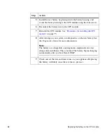
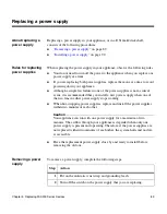
Page 101: ...s is not a critical event it is recommended that you install a new power supply when one of the two fans in either power supply stops working When hot swapping power supplies replace and install the p...

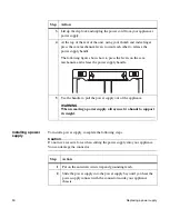
Page 102: ...er press the cam mechanism levers toward each other to release the power supply handle The following figure shows how to press the levers on the cam mechanism and release the power supply handle 5 Use...

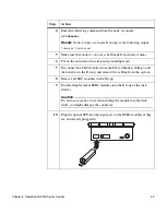
Page 103: ...he handle into place 4 Plug the power cord into the power receptacle and fasten it with the clamp 5 Plug the other end of the power cord into a grounded AC power source 6 Turn on the power switch and...

Page 104: ...lf that does not have multipath connections you lose all access to the drives on that disk shelf as well as those connected below it Replacing the modules To replace the LRC modules with ESH2 modules...

Page 105: ...ap and grounding leash 7 Disconnect the LRC modules from the Fibre Channel cabling on all disk shelves in the B loop and remove the cabling from the system 8 Remove all LRC modules in the B loop 9 Ins...

Page 106: ...d modules for a Then FAS270 system Turn on the power and reboot the system FAS270c system Give back the partner node by entering the following command cf giveback Result The local node releases the pa...

Page 107: ...102 Netboot process for the FAS200 series on page 107 Booting your appliance from a backup firmware image on page 109 Troubleshooting hardware problems on page 110 Where to get more information The f...

Page 108: ...ies of messages are examples of POST messages displayed on the console Header CFE version 1 1 0 based on Broadcom CFE 1 0 35 Copyright C 2000 2001 2002 2003 Broadcom Corporation Portions Copyright C 2...

Page 109: ...Host Adapter 0c slot 0 SB1250 Gigabit Dual Ethernet Controller e0a MAC Address 00 a0 98 00 e9 b3 auto unknow e0a MAC Address 00 a0 98 00 e9 b4 auto unknow slot 0 NetApp ATA IDE Adapter 0a 0x000000000...

Page 110: ...tration host is given root access to the filer s etc files for system administration To allow etc root access to all NFS clients enter RETURN below Please enter the name or IP address of the administr...

Page 111: ...t is jumping to executable code This is not an error but rather a progress state indicator used to help troubleshoot the problem HELO Very early Init code If the system stops on one of these error cod...

Page 112: ...ng the SDRAM DIMM on the CPU module on page 81 Zero Zero memory no NVMEM Keep Keep memory preserve NVMEM ZBSS Zero the BSS segment CODE Zero and copy the code segment from flash to memory DATA Zero an...

Page 113: ...odes there is likely a problem with either the SB1250 chip or the ISP2312 FC AL chip 1 Try booting with the backup firmware image See Booting your appliance from a backup firmware image on page 109 2...

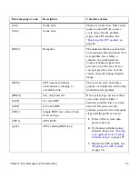
Page 114: ...fru_name STRING This is a warning message that is issued when a chassis fan is spinning too slowly The fan unit should be replaced LOG_ALERT Chassis FRU contains at least one fan spinning slowly 365 C...

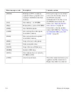
Page 115: ...ture is too warm 372 Chassis temperature is too warm monitor chassis Temperature co ol ALERT describe_ toocool STRING This is a warning message that is issued when the chassis temperature is too cool...

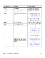
Page 116: ...NFO CPU Fan OK 386 CPU Fan OK monitor cpuFan degraded NOTICE cpu_number INT This message indicates that a CPU fan is degraded The CPU fan or the system motherboard might need to be replaced See the ha...

Page 117: ...sage indicates that a power supply is not present Add a power supply to the appliance LOG_NOTICE Chassis power supply not present 394 Chassis power supply is not present monitor chassis PowerSupply de...

Page 118: ...eplacing them to see whether that alleviates the problem Otherwise contact technical support for further instruc tion monitor chassis Power degraded NOTICE reasonText STRING This message indicates tha...

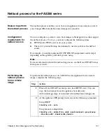
Page 119: ...For example you might configure BOOTP DHCP bootparamd and or rarpd depending on the specific procedure you are using Note For more information about the netbooting process see the Data ONTAP Storage M...

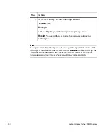
Page 120: ...ownload command to copy the correct files from the disks to the CompactFlash card See the Data ONTAP System Administration Storage Management Guide for more details 3 At the CFE prompt enter the follo...

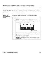
Page 121: ...ware image To boot using a backup firmware image complete the following steps Step Action 1 With the system powered off insert a paper clip into the tiny unmarked hole between the console and Ethernet...

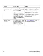
Page 122: ...tip on the list until the problem is solved Unplug the battery in the CPU module for 5 seconds plug the battery back in and try booting the appliance Note Unplugging the battery might reset the clock...

Page 123: ...the battery back in to the motherboard and reset the clock to the correct time The appliance does not recognize any of the installed disk drives The 1 Gb 2 Gb switch is not set to the 1 Gb position 1...

Page 124: ...on the battery charger You have two main options at this point 1 Leave the appliance alone for a few hours to let the battery charge 2 Press Ctrl C to override this check Contact technical support if...

Page 125: ...p including the CPU module must have the terminate switches set to OFF If that doesn t fix it you might have a faulty shelf drive or cable Try removing items until the loop closes and then add them ba...

Page 126: ...114 Troubleshooting hardware problems...

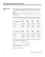
Page 127: ...endix A Recommended Power Line Sizes 115 A Recommended Power Line Sizes About this appendix This appendix discusses how to determine the power line lengths running from your appliance to the power sou...

Page 128: ...the recommended conductor size for 2 voltage drop for a particular distance in feet taken from the Radio Engineer s Handbook The following table list the approximate equivalent wire gauge American Wir...

Page 129: ...dix B Communications Regulations 117 B Communications Regulations About this appendix This appendix lists the regulatory notices you need to be aware of when installing and operating your NetApp equip...

Page 130: ...with Part 15 of CFR 47 This equipment has been tested and found compliant with Part 15 of the CFR 47 rules for Class A digital devices These rules are designed to provide reasonable protection from in...

Page 131: ...a domestic environment this product may cause radio interference in which case the user may be required to take adequate measures Voluntary Control Council for Interference by Information Technology E...

Page 132: ...0 3 3 1995 A1 2001 Limitation of Voltage Fluctuations and Flicker in Low Voltage Supply Systems following the provisions of the directives listed below 73 23 EEC Low Voltage Directive Product Safety 8...

Page 133: ...ted to include environmental EMS messages Procedure for replacing LRC modules with ESH2 modules Data ONTAP 7 0 October 2004 Consolidated FAS250 FAS270 and FAS270c information into one hardware guide D...

Page 134: ...122 Feature Update Record...

Page 135: ...k shelf 13 nonclustered network 3 power 26 storage appliance to power source 26 tape backup device 28 third party device 27 conventions command viii formatting viii keyboard ix CPU module battery pack...

Page 136: ...operation panel 55 power supply 58 LED locations CPU module 61 disks 59 Ethernet 61 FAS250 CPU module 63 FAS270 Fibre Channel 61 front operation panel 54 power supply 57 loop speed 17 22 24 LRC to ESH...

Page 137: ...tch for 91 removal of 89 rules for replacing 89 R removal of CompactFlash card 83 CPU module 70 disks 66 power supplies 89 replacement of appliance devices 65 battery 86 CompactFlash card 83 CPU modul...

Page 138: ...126 Index terminology vii third party devices preparing 27 rules for connecting 27 supported interface for 27 troubleshooting 95 110...

Reviews: