SmartNA-X 1G/10G Modular | V-Line Module Specifications |
187
SmartNA-X
™
1G/10G User Guide 1.4
©
2015 Network Critical Solutions Limited
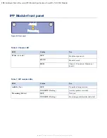
V-Line Module LED Indicators
Figure 81: V-Line front panel ports
Note that the reset push button is not currently available.
Port LED Status Indicators
LED
Description
Type
Use
POWER
Module power status
Blue /
Red
OFF
Module not powered or booted
RED
Chassis 12V detected, module not booted
BLUE
Module booted OK
LNK
(Right) Link Status/Activity (per
port, all ports)
Green
OFF
Not Linked
ON
Linked; Traffic (flashing)
LFP
(Left)
Link Fail Propagation (per
port, A and B only)
Green
OFF
Normal operation
GREEN
LFP has forced this port down
HB
(Left)
Heartbeat OK (per port, C
and D only)
Green
OFF
No Heartbeat being received
GREEN
Heartbeat being received OK
Bypass LED status indicators
LED
V-Line Mode
Breakout/Aggregation TAP Mode
A=B (Top)
Port A B Bypass State:
OFF
Auto mode, tool in-line
YELLOW
Bypass Triggered
(Port A connected to Port B)
GREEN
[Not Used]
Port A B Bypass State:
OFF
[Not Used]
YELLOW
[Not Used]
GREEN
Port A connected to Port B
A≠B
Port A B Bypass State:
OFF
Auto mode, tool in-line
Port A B Bypass State:
OFF
[Not Used]
YELLOW
[Not Used]


