66
| Working with the V-Line Module | SmartNA-X 1G/10G Modular
SmartNA-X
™
1G/10G User Guide 1.4
©
2015 Network Critical Solutions Limited
•
Breakout A → C
—Select the check box to add a breakout mapping from Port A to Port C. Traffic received on A
is copied to C.
•
Breakout B → D
—Select the check box to add a breakout mapping from Port B to Port D. Traffic received on B is
copied to D.
•
Slicing (A ingress)
—Enter a packet slicing size for ingress traffic received on Port A. Minimum slicing size is 16
Bytes and maximum slicing size is 9216 Bytes. Leave blank or enter 0 to keep packets unsliced. This setting only
affects ingress packets that are copied from the A/B ports to ports on other cards.
•
Slicing (B ingress)
—Enter a packet slicing size for ingress traffic received on Port B. Minimum slicing size is 16
Bytes and maximum slicing size is 9216 Bytes. Leave blank or enter 0 to keep packets unsliced. This setting only
affects ingress packets that are copied from the A/B ports to ports on other cards.
•
Slicing (C egress)
—Enter a packet slicing size for egress traffic sent from Port C. Minimum slicing size is 16
Bytes and maximum slicing size is 9216 Bytes. Leave blank or enter 0 to keep packets unsliced.
•
Slicing (D egress)
—Enter a packet slicing size for egress traffic sent from Port D. Minimum slicing size is 16
Bytes and maximum slicing size is 9216 Bytes. Leave blank or enter 0 to keep packets unsliced.
4.
Configure port communication settings, noting the following requirements for effective port communications:
Mapping to other TAP modules
If a V-Line module is mapped to another TAP module, the V-Line module ports must be set to 1G bps.
Live ports
If operating in V-Line, Aggregation or Breakout mode, the V-Line module live ports (
A
and
B
) must have
matching communication settings (same speed, duplex and MDI settings).
Tool ports
If operating in V-Line or Breakout mode, the V-Line module tool ports (
C
and
D
) must have the same
communication settings as the live ports (
A
and
B
) .
5.
Click
Review/apply
and review pending changes. To apply these changes to the system, click
Apply changes
or click
'
X
' to cancel.
Configure Aggregation mode
1.
Click on the V-Line module you wish to configure and select the
V-Line
tab.
2.
From
V-Line mode
, select
Aggregation
. The
V-Line Module: Aggregation mode
dialog is displayed (see the figure
below).
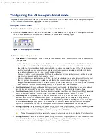
Figure 60: V-Line Module: Aggregation mode settings dialog
3.
Enter the values for the parameters.
•
Aggregate A+B → C
—Select the check box to merge Ports A and B and send to Port C.
•
Aggregate A+B → D
—Select the check box to merge Ports A and B and send to Port D.

