SDI-TD-DMUX-4
Rev.
5
5
Front Panel LEDs
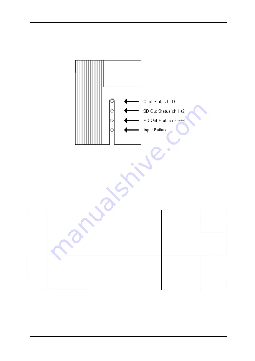
Figure 7 shows how the LEDs are located on the front panel.
Figure 7: Front Panel View with LED Indicators
The table below shows how the front panel LEDs are to be interpreted.
Note that the term “in error” in the table means that there is either a missing signal (data in
transport stream) AND/OR the re-clocker has not been able to lock to the received signal.
The term “operating normally” means that a signal has been detected (data available in the
transport stream) AND the re-clocker has been able to lock to the signal.
The term “Input failure” means that there is either a missing signal (no carrier detect)
AND/OR the re-clocker has not been able to lock to the incoming signal.
Diode Description
Red
LED Orange LED
Green LED
No light
1 Card
Status
Power on, FPGA
not configured
Not
applicable
Power on and
FPGA
configured
Board not
powered
2
SD OUT 1
and
SD OUT 2
(see note below)
Both channels
(1 and 2)
in error
One of the
channels
(1 or 2)
in error
Both channels
(1 and 2)
operating
normally
Not
applicable
3
SD OUT 3
and
SD OUT 4
(see note below)
Both channels
(3 and 4)
in error
One of the
channels
(3 or 4)
in error
Both channels
(3 and 4)
operating
normally
Not
applicable
4 HD
IN
(see note below)
Input failure
Not
applicable
Input OK
Not
applicable
Note: When the HD IN led is red due to a missing or corrupt HD input signal, diode 2 and 3
will automatically turn red too, even if a generator signal is available on the output.
network-electronics.com | 15


