background image

network-electronics.com

2x1/2x2 Wideband Optical 

Switch 

Rev. 6

Flashlink User Manual

WOS-2x1/WOS-2x2

WOS-2x1L/WOS-2x2L

Summary of Contents for WOS-2x1

Page 1: ...network electronics com 2x1 2x2 Wideband Optical Switch Rev 6 Flashlink User Manual WOS 2x1 WOS 2x2 WOS 2x1L WOS 2x2L...

Page 2: ...ble below Revision Replaces Date Change Description 6 5 2007 10 30 AS New front page and removed old logo 5 4 2007 10 05 AS Added Materials Declaration and EFUP 4 3 03 11 13 RS Corrected GPI desc for...

Page 3: ...non latching trigger type 8 4 2 GPI Module Status Outputs and switch alarm trigger inputs latching trigger type 9 4 3 Front Panel Status Monitoring 10 4 4 GYDA System Controller 11 4 5 RS 422 command...

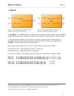
Page 4: ...lications for these units are selective routing of optical signal paths without optical to electrical conversion and Automatic Protection Switching APS The units are controlled via the flashlink GYDA...

Page 5: ...tor return loss 40dB w SM fiber Cross talk 80dB Repeatability 0 01dB Durability 10 000 000 cycles Switching time 50ms typ Switching time latching versions 200ms typ Connector SC UPC 62 5 125um Multi m...

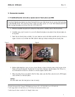
Page 6: ...ard in the actual slot from earlier carefully remove this board first 2 Carefully remove all 4 screws 2 screws if a blank back plane is mounted from the back plane to be replaced 3 Insert the new back...

Page 7: ...e as seen from the rear a rubber plug must replace the spring loaded plastic shield of the fiber adapter 3 2 Applying signals to the connector module The optical connection is an SC UPC connector with...

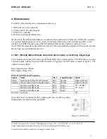
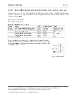
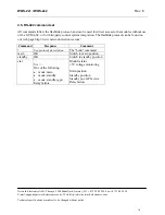
Page 8: ...ller is described in section 4 4 The commands the modules will respond to over the RS 422 bus can be found in section 4 5 4 1 GPI Module Status Outputs and switch alarm inputs non latching trigger typ...

Page 9: ...shown in figure 6 The connector used is RJ 45 Max output current 100mA Max output voltage 30V WOS 2x1 WOS 2x2 GPI pinning Signal Name Pin Input Output Mode Status General error status for the module...

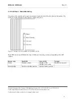
Page 10: ...ring The status of the module can be easily monitored visually by the LEDs at the front of the module The LEDs are visible through the front panel as shown in figure 6 Figure 7 Diode overview of WOS 2...

Page 11: ...iguration Settings Manuals All user manuals in PDF format About The description of the GYDA System Controller is found in a separate user manual The GYDA System Controller has two different pages for...

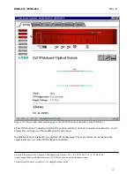
Page 12: ...ct to be changed without notice 12 Figure 10 The module information page in the GYDA System Controller of the WOS 2x2 The GYDA System Controller identifies the position and the type of each module aut...

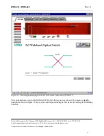
Page 13: ...electronics com Technical specifications are subject to be changed without notice 13 Figure 11 The configuration page in the GYDA System Controller of WOS 2x2 The configuration screen for the WOS 2x1...

Page 14: ...can be used for direct access to the modules without use of the GYDA SC or for third party control system integration The flashlink protocol can be found on our web page http www network electronics...

Page 15: ...re subject to be changed without notice 15 5 Configuration and application examples 5 1 Automatic Protection Switching with WOS 2x1L Figure 12 Possible setup for APS functionality standby fiber is not...

Page 16: ...ical specifications are subject to be changed without notice 16 5 3 DWDM Automatic Protection Switching with WOS 2x1L Figure 15 DWDM with APS without monitoring of standby fiber main position 5 4 DWDM...

Page 17: ...00 nm to 700 nm A laser beam can be harmful to the human eye depending on laser power and exposure time Therefore BE CAREFUL WHEN CONNECTING DISCONNECTING FIBER PIGTAILS ENDS NEVER LOOK DIRECTLY INTO...

Page 18: ...ereby complies with the Electromagnetic Compatibility Directive 89 336 EEC General environmental requirements for flashlink equipment 1 The equipment will meet the guaranteed performance specification...

Page 19: ...www network electronics com Technical specifications are subject to be changed without notice 19 Product Warranty The warranty terms and conditions for the product s covered by this manual follow the...

Page 20: ...This is defined as the period of normal use before any hazardous material is released to the environment The guidance on how the EFUP is to be calculated is not finalised at the time of writing See h...

Page 21: ...ted for 50 years Recycling information Network Electronics provides assistance to customers and recyclers through our web site http www network electronics com Please contact Network Electronics Custo...

Reviews: