WOS-2x1 / WOS-2x2
Rev. 6
Network Electronics ASA, Thorøya, 3204 Sandefjord, Norway, Tel.:+47 33 48 99 99 Fax: +47 33 48 99 98
E-mail: support@network-electronics.com - Web: http://www.network-electronics.com
Technical specifications are subject to be changed without notice
9
4.2 GPI – Module Status Outputs and switch alarm trigger inputs, latching trigger type
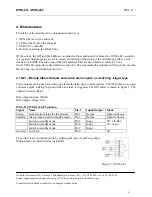
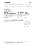
These outputs can be used for wiring up alarms for third party control systems. The GPI output is an open
collector output, sinking to ground when an alarm is triggered. The GPI outlet is shown in figure 6. The
connector used is RJ-45.
Max output current: 100mA
Max output voltage: 30V
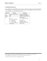
WOS-2x1/WOS-2x2 GPI pinning:
Signal Name
Pin
# Input/Output Mode
Status
General error status for the module
Pin 1
Output
Open Collector
Standby Alarm when switch in standby mode
Pin 2
Output
Open Collector
Switch to standby mode
Pin 5
Input
Reset switch to main position
Pin 6
Input
Reset switch to main position
Pin 7
Input
0V= standby
5V= main
Ground 0 volt pin
Pin 8
0V
The switch is set in standby mode by sinking pin5 to ground. Pin6 and
pin7 are hardwired as logical OR and when either is sunk to ground, they
will reset the latching switch to main position. Resetting can also be done
with GYDA system controller.
Figure 6: GPI Outlet


