D-422-MG
Rev.
0
9
3.3
RS-422 Connector Pin Assignments
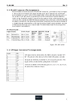
RS-422 shall be connected to one of the RS-422 connectors, positioned as shown in figure
2. The connectors are RJ-45 style, 8-pin modular jacks. Each connector has two RS-422
ports, referred to as ports 1 and 2 in the below table. In the event that only one port is in
use, an RJ-11 style 4/6 (4-wire, 6-position) jack can be used instead. Signals marked as
inputs on the D-422-MG shall be connected to the outputs of the connected devices, and
vice versa. The columns for DB9 VTR Master and Slave show which pin on the 9 pin DSUB
should be connected to the signal. Note that when connecting an active device instead of
a straight-through cable between a VTR master and slave (device and controller), one end
of the active device must use a crossed cable. The table below takes the crossing on the
slave side into consideration.
RS-422 pin layout:
Signal Name
Port1 Port2 DB9 VTR
Master
DB9 VTR
Slave
Mode
RX +
Receive Pos.
Pin 3 Pin 1
Pin 3
Pin 7
Input
RX -
Receive Neg.
Pin 6 Pin 2
Pin 8
Pin 2
Input
TX +
Transmit Pos. Pin 5 Pin 7
Pin 7
Pin 3
Output
TX -
Transmit Neg. Pin 4 Pin 8
Pin 2
Pin 8
Output
Figure 3 RS-422 outlet
3.4
GPI Input Connector Pin Assignments
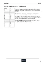
GPI inputs shall be connected to the DB25 connector marked “GPI
IN”. The pinout is the same as for the VikinX GPI panels, see table.
All inputs are internally connected to +5V via a pull-up resistor. The
inputs will be activated when pulling them to Ground.
Ground is available on the following pins: 2, 5, 8, 11, 13, 16, 19, 22,
25 and on the connector chassis.
Input Pin
1 12
2 24
3 23
4 10
5 9
6 21
7 20
8 7
9 6
10 18
11 17
12 4
13 3
14 15
15 14
16 1


