ArchiTech Cylindrical Lock & Surface-Mounted Networx Control Unit Mounting and Installation Instructions
10
11C.
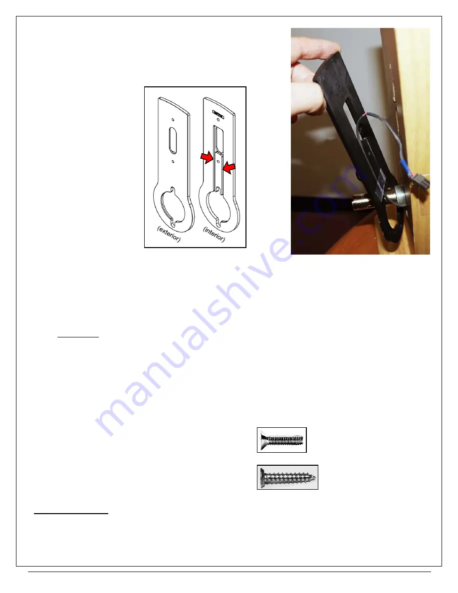
Route
the
Cylindrical Lock Motor Wire
within one of the two
grooves located on the "interior" of the
Wiring Plate
; use the
groove on the same side as the
Motor Wire
as it exits the
Lock
Body
. Tape the wire in place.
Note:
The
Cylindrical Lock Motor Wire
plug sleeve color is
yellow
.
11D.
Place the circular opening of the
Wiring Plate
over the inside ("protected" side) so that its "interior" grooves will
rest against the inside door surface.
Use a level
to ensure the
Wiring Plate
is vertical; use a pencil to mark its two mounting holes in the
door surface.
11E.
Drill the two pilot holes for the
Wiring Plate
mounting screws (NOT thru-holes) using a 7/64" drill bit. Drill only
into the inside door
surface
(NOT thru-holes).
11F.
Secure
the
Wiring Plate
to the door using the two Phillips Flat Head screws appropriate for the door type as
follows:
For Metal Doors:
#6-32 x 5/8" long Type 23 thread
cutting Phillips Flat head, U-cut (part #SC682);
For Wood Doors:
#6 x 3/4" long undercut self-
tapping Type A Phillips head (part #SC596)
Skip to step 13
.
FIG. 11C: USE THE GROOVE ON THE
SAME SIDE AS THE MOTOR WIRE
(ARROWS)
FIG. 11CC: ROUTE THE MOTOR WIRE
WITHIN THE GROOVE CLOSEST TO THE
MOTOR WIRE. TAPE WIRE IN PLACE


