19
ArchiTech Cylindrical Lock & Surface-Mounted Networx Control Unit Mounting and Installation Instructions
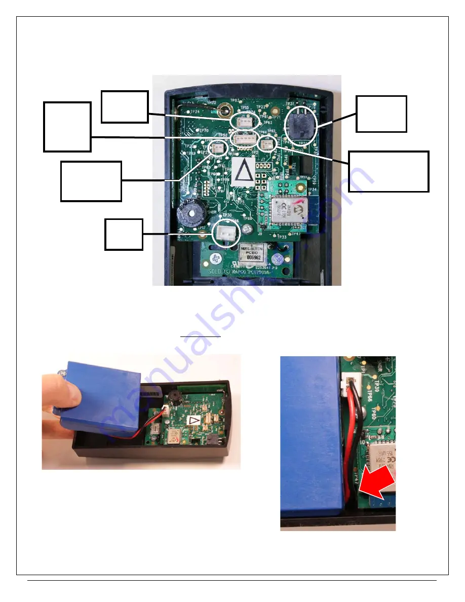
17. CONNECT PLUGS IN THE "SURFACE-MOUNTED NETWORX CONTROL UNIT"
Match the plug sleeve colors to the corresponding sockets (see Fig. 17).
Note:
The Door Contact Sensor is a pair of
white wires connected to a small white plug with a blue sleeve near the sensor; do not confuse this plug with the plug for
the "RX Request to Exit" plug originating from the
Cylindrical Lock Body
.
18. CONNECT THE BATTERY PACK
See the above Fig. 17 for the location of the
Battery Pack
socket. Place the
Battery Pack
into the rear of the
Surface-
Mounted Networx Control Unit
with the flat side up, as shown in Fig. 18A. As shown in Fig. 18B, route the wires
through the opening in the PCB. This opening was intentionally designed to prevent pinched wires.
FIG. 18A: INSTALL BATTERY PACK WITH FLAT SIDE UP
FIG. 17: CONTROL UNIT CONNECTIONS
(YELLOW)
Lock Motor
Wire
(
J2)
Battery
Pack
(ORANGE)
Proximity
Reader
(
J5)
(BLUE)
LEDs
(
J1)
(WHITE)
Door Contact
Sensor
(
J3)
RX Request to Exit
(for locks so
equipped)
(
J6)
FIG. 18B: BE SURE WIRES ARE
ROUTED THROUGH PCB OPENING
(ARROW). Do NOT pinch wires!


