
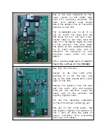
Now
on
to
most
of
the
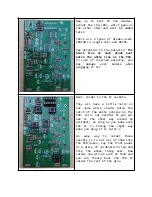
diodes,
except the LED (D9), which goes on
the other side and will be added
later.
There are 2 types of diodes used:
1N4148 (a single one) and BAT85.
Pay attention to the polarity: The
black
line
on
each
diode
must
match the white line on the PCB.
In case of reversed polarity, you
may
damage
your
module
when
plugging it in!
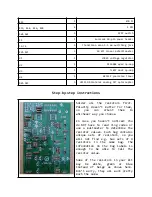
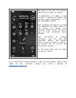
Next, solder in the IC sockets.
They all have a little notch on
one side which should match the
notch of the white outline on the
PCB. (It’s not harmful if you put
one in the other way around by
accident, as long as you make sure
the IC is facing the right way
when you plug it in later.)
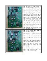
An
easy
way
to
solder
those
sockets is to set all of them into
the PCB holes, lay the front panel
or a piece of cardboard on top and
flip
the
whole
thing
over.
Now
solder one pin of each of them and
you can freely move the PCB to
solder the rest of the pins.


