background image

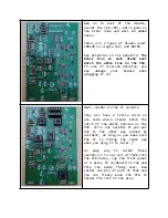
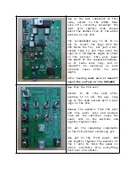
Add the 2x5 pin power header in
the top left and the capacitors.

You can solder the small (0.1 µF)
capacitors

first,

so

they

won’t

fall out after fitting the larger
ones and flipping the board for
soldering. Or just fit them all at
once and bend their legs slightly.

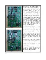
Polarity matters for almost all of
the

capacitors

except

for

C12,

which

is

a

bipolar

electrolytic

one. It does have one short and
one long leg, but the orientation
doesn’t matter. However, make sure
not to confuse C12 with any of the
other 1 µF capacitors
!

The long legs go on the plus side
as indicated on the PCB.

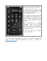
Now for the easiest part: Plug the
ICs into their sockets.

They all have a little dot on them
which

should

match

the

little

notch on the IC socket (and the
notch in the white outline on the
PCB).

Bend their legs slightly inward if
you have trouble fitting them in.

Make

sure

not

to

confuse

the

NE555P

with

the

TL072,

as

both

have 8 legs.

The H11F1M in your kit may not be
white,

but

black

instead.

Don’t

worry, they work the same.

Summary of Contents for NERMAL

Page 1: ...ount but please go through this guide at least quickly to make sure you re not missing anything Important DO NOT EMPTY ANY OF THE COMPONENT BAGS NOW The components are grouped into the bags so that all of them can be identified without having to look up resistor ring codes Rather leave everything inside the bags and take out what you need while soldering ...

Page 2: ... electrolytic 10 µF C3 C11 2 electrolytic 1 µF C4 C6 C8 C10 5 electrolytic 0 1 µF C5 1 electrolytic 47 µF C7 1 electrolytic 4 7 µF C12 1 electrolytic bipolar 1 µF C13 1 electrolytic 2 2 µF D1 D8 D11 D12 10 BAT85 Schottky diode D9 1 LED 3 mm orange D10 1 1N4148 signal diode R1 R3 R9 R10 R16 R20 R25 8 10 kΩ R4 R32 2 2 2 kΩ R5 R8 4 220 kΩ R11 1 47 Ω R12 R14 3 100 Ω R15 R29 R33 R34 4 1 kΩ R17 R30 2 10...

Page 3: ...older all the resistors first Polarity doesn t matter for them so you can orient them in whichever way you choose In case you haven t noticed You do NOT have to read ring codes or use a multimeter to determine the resistor values Each bag contains unique sets of resistors so you will not find e g two sets of 4 resistors in the same bag The information on the bag labels is enough to be able to tell...

Page 4: ...Next solder in the IC sockets They all have a little notch on one side which should match the notch of the white outline on the PCB It s not harmful if you put one in the other way around by accident as long as you make sure the IC is facing the right way when you plug it in later An easy way to solder those sockets is to set all of them into the PCB holes lay the front panel or a piece of cardboa...

Page 5: ...long leg but the orientation doesn t matter However make sure not to confuse C12 with any of the other 1 µF capacitors The long legs go on the plus side as indicated on the PCB Now for the easiest part Plug the ICs into their sockets They all have a little dot on them which should match the little notch on the IC socket and the notch in the white outline on the PCB Bend their legs slightly inward ...

Page 6: ...t it shouldn t be necessary as most Eurorack cases offer far more depth After bending make sure it doesn t touch the surface of the MCP6004 Now flip the PCB over Solder in D9 the LED after pushing it in all the way long leg on the side marked with a plus sign on the PCB Remove the washers from the pots and the outer nuts and washers from all the switches Leave the lower nuts on the switches and li...

Page 7: ...solder can reflow Also visually inspect joints and see if you can spot accidental solder bridges When everything is working correctly you can add the remaining washers and tighten them If using a wrench or pliers be careful not to scratch the front panel surface As the final step put the knobs on the pot shafts If you need help troubleshooting or want to share photos audio and or video of your cre...

Reviews: