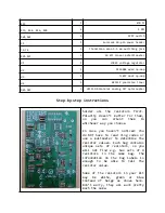
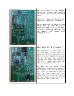
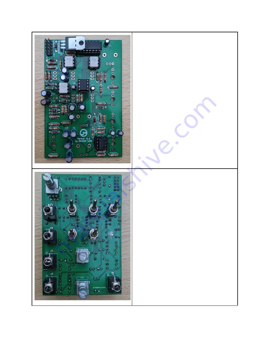
Now as the last component on this
side, solder in the L7805. Make
sure it’s correctly oriented: The
heat
sink
(metal)
side
should
match the double line of the white
outline on the PCB.
The recommended way to do it is
not to insert the legs into the
PCB holes too far, but just a bit,
solder them in and then bend the
legs at a 90 degree angle as shown
in the picture. This will lower
the depth of the completed module,
so
it
looks
more
tidy.
But
it
shouldn’t
be
necessary
as
most
Eurorack
cases
offer
far
more
depth.
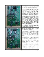
After bending make sure it doesn’t
touch the surface of the MCP6004!
Now flip the PCB over.
Solder
in
D9
(the
LED)
after
pushing it in all the way, long
leg on the side marked with a plus
sign on the PCB.
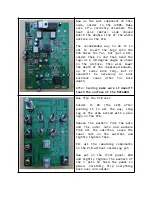
Remove the washers from the pots
and
the
outer
nuts
and
washers
from all the switches. Leave the
lower
nuts
on
the
switches
and
lightly tighten them.
Fit all the remaining components
on the PCB without soldering yet.
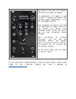
Now put on the front panel. Add
and lightly tighten the washers of
the 3 pots to hold the panel in
place.
Carefully
flip everything
back over and solder.