Page 7 of 13
NPPA-TT-PT Instruction Manual
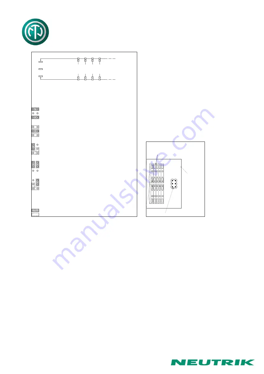
Common Signal Ground
Common Signal Ground
Bottom Row
Chassis Ground
Top Row
Grounding Variations (PT version)
Soldering Pads
Individual Grounds to Common Ground
to connect
Common Signal Grounds of
Top and Bottom Row separated
Jumper Setting for Group, Central & Chassis Common
Common Signal Ground Bottom Row
connected to Chassis Ground
Common Signal Ground Top Row
connected to Chassis Ground
Common Signal Ground Top and Bottom Row
connected to Chassis Ground
connected together and separated from Chassis Ground
Common Signal Ground of Top and Bottom Row
... Position has no Influence to the Grounding
... Needed Jumper Position for certain Grounding
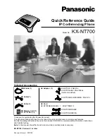
Position of Pin-Header on PCB
edge of PCB
Push Terminals
Arrangement
Grounding Variations
Pin Header
NOTE
: In standard configuration there is no ground connection between top and bottom row
unless it is provided by an inserted patch cable. If this is required, as in the case of
phantom powered microphone lines, either make an internal connection by individually
wiring the corresponding upper and lower ‘S’ terminals, or if the latter is critical with
respect to possible ground loops make the connection via patch cable
instead of using
the normalling feature
.


