Page 8 of 13
NPPA-TT-SD25 Instruction Manual
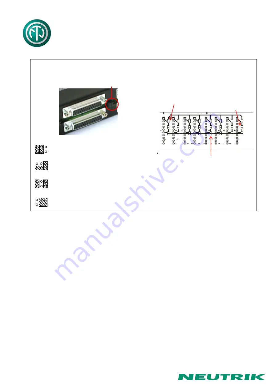
Jumper Setting
Arrangement on PCB
(seen from mating side)
Chassis Common
Sub-D-Group Central
Sub-D-Group Chassis Top
Sub-D-Group Chassis Bottom
Grouping
PCB
(seen from front, removed jack pairs)
flexible foil
Bridge sleeve
It's also possible to bridge the sleeve contacts
of top and bottom row without grouping of
channels!
Grounding Variations
Note:
Phantom powered microphones
In general it is not recommended to run phantom power through patch panels.
In the case it is required to patch phantom powered microphones, all of the shields (SLEEVE contacts)
from this device must be tied together. This can be accomplished by grouping the grounds of these
channels via the PCB bus (using solder bridges). This group is then connected onto the general technical
ground. Because of the missing SLEEVE normalling contact it is necessary to wire internally the ground
(sleeve) contact of the top and bottom row of each channel. If this is critical with respect to possible
ground loops make the connections via patch cable instead of using the normalling feature.
Pin-Header
Ground grouping
top row
Ground grouping
bottom row
Solder to
bridge sleeve
(phantom power)


