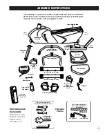
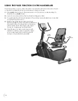
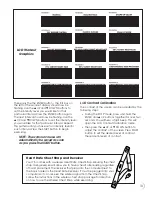
background image

a)

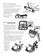
Remove the Plastic Stoppers and the two small Phillips
Screws at the back of the Seat Carriage Tube. Slide off the
Carriage End Cap letting it gently hang.

b)

Holding the Seat Carriage Assembly by the front of Seat
Cushion and the top of the Back Rest, slide it onto the Seat
Carriage Tube. Lift up on the Seat Carriage Locking Knob
and slide the Seat Carriage Assembly on the Seat Carriage
Tube until the Seat Carriage Locking Knob locks into a slot.

c)

Replace the Plastic Stoppers, Carriage
End Cap and Phillips Screws you
removed in (a).

d)

Plug the wire from the rear of the
Seat Carriage Tube into the wires
coming from the Handlebar on
the lower back of the Seat
Carriage Assembly.

STEP 3 – Handlebar Tube Assembly

a)

Remove the two Allen Bolts, Washers and Phillips Screw 
from the Handlebar Tube.

b)

Slip the Handlebar Tube Cover onto the Handlebar Tube as shown.

The Handlebar Tube should lean back towards the back of unit.

c)

Remove the wire tie from the wires inside the Main Frame Assembly
where the Handlebar Tube will go. Attach the four wires from the
Main Frame Assembly to the four wires coming out the bottom of
the Handlebar Tube.

d)

Insert the Handlebar Tube into the Main Frame Assembly, tucking
the wires down into the Main Frame Assembly. Reinsert the Allen
Bolts and Washers you removed in (a).

Be careful not 

to pinch the wires. NOTE: Gently pull the wires up from the
top of the Handlebar Tube to prevent any slack in the
wires at the base of the Handlebar Tube.

Hand tighten.

e)

Secure the Handlebar Tube in place with the 
three Allen Bolts, Washers and Nylon Nuts from 
the Fastener Pack. Tighten with the Wrench provided.
Also tighten the bolts used 
in step (d).

f)

Let the Handlebar Tube Cover
slip into place. Push it down 
gently until it clicks. Secure in
place with the Phillips Screw 
you removed in (a).

handlebar

tube

allen bolts,

washers & nuts

from fastener

pack

opening in

handlebar tube

towards back

main

frame

assembly

back of unit

re-insert allen

bolts & washers

from step a

remove allen

bolts & washers

phillips

screw

handlebar

tube

cover

M8 x 60mm allen bolts,

M8 washers and M8 nylon nuts

7

3d

3a

3c

3d

3e

3b

STEP 5 – Foot Pedal Assembly

The Foot Pedals and the Foot Pedal
Cranks are marked “L” and “R”.

Using the Wrench provided, attach the

left

Foot Pedal to the 

left

Crank rotating

the Wrench 

counter-clockwise

.

Do not try to turn clockwise. You will 
strip the threads.

Attach the 

right

Foot Pedal to the 

right

Crank rotating the Wrench 

clockwise

.

left side shown

looking from the

back of the unit

left
crank

“L” & “R”
markings are
located on the
ends of the
pedal shaft.

left foot

pedal

STEP 4 – Seat Carriage Assembly

4a

4b

4c

phillips

screw

plastic stoppers

wire

4d

seat carriage

tube

seat carriage

locking knob

carriage
end cap

Summary of Contents for 7.5r

Page 1: ...OWNER S MANUAL FOR MAXIMUM EFFECTIVENESS AND SAFETY PLEASE READ THIS OWNER S MANUAL BEFORE USING YOUR NEW BALANCE 7 5r Recumbent Bike 7 5r...

Page 2: ...5 Measuring Your Heart Rate 15 16 Clothing 16 Tips to Keep You Going 16 Heart Rate Target Zone Chart 17 Warm Up Cool Down Stretches 18 19 Care Storage Of Your New Balance 7 5r 20 Workout Progress Char...

Page 3: ...your breath during an exercise 7 Avoid over training You should be able to carry on a conversation while exercising 8 After an exercise session cool down with slow walking and stretching 9 This machi...

Page 4: ...AY RESULT IN POSSIBLE SERIOUS INJURY OR DEATH KEEP CHILDREN AWAY MAXIMUM USER WEIGHT 300 LBS REPLACE THIS LABEL IF DAMAGED ILLEGIBLE OR REMOVED WARNING WARNING LABEL 1 Book Holder WARNING LABEL 1 WARN...

Page 5: ...r 2 Date of Purchase 3 Where Product was Purchased Name of Retail Store City 4 Model Number NBP01075 2 5 Part Order Number and Description With this product in your home you have everything you need t...

Page 6: ...ot tube with rollers L R foot pedals straps seat cushion back rest front handlebar seat carriage slider and seat adjustment knob seat carriage seat carriage locking knob handlebar tube cover rear hand...

Page 7: ...Washers and Hex Nuts from your Fastener Pack Tighten bolts with the Wrench provided b Place the Seat Cushion on a flat surface Position the Seat Carriage with the wheels up as shown Secure with Philli...

Page 8: ...llen Bolts and Washers you removed in a Be careful not to pinch the wires NOTE Gently pull the wires up from the top of the Handlebar Tube to prevent any slack in the wires at the base of the Handleba...

Page 9: ...to the Handlebar Tube by re inserting Phillips Screws and tightening them with the Screwdriver provided book holder connectors handlebar tube computer Front View 4 1 3 2 four C batteries back of comp...

Page 10: ...etely smooth and natural feeling that minimizes the impact on your hips knees and ankles while providing a superior aerobic and muscle toning workout The durable steel frame and transport wheels make...

Page 11: ...r pulse window The small heart will begin to blink 3 Your estimated heart rate will appear in the window approximately 6 seconds after you grasp the pulse sensors 4 Refer to the Target Heart Rate Zone...

Page 12: ...n AGE Your computer is age programmable from 10 to 99 years when you choose all programs except Program 8 When using Program 8 you will set Target Heart Rate instead of Age Note This unit is not recom...

Page 13: ...tance on the next interval By the resistance changing the machine will be able to keep your heart rate close to the target beats per minute When used properly the heart rate pulse sen sors and display...

Page 14: ...by the following steps During the STOP mode press and hold the ENTER and UP buttons together for over two seconds You will hear a faint beep This will open the LCD Contrast Calibration mode Then pres...

Page 15: ...ove wastes over sustained periods of time Using your New Balance 7 5r will improve this MUSCULAR STRENGTH the ability of a muscle to exert force for a brief period of time Upper body strength for exam...

Page 16: ...intensity vigorous enough to cause your heart rate and breathing to increase How hard you should exercise depends to a certain degree on your age and is determined by measuring your heart rate in bea...

Page 17: ...e a reasonably accurate estimate of your actual heart rate This estimate is not exact and persons with medical conditions and or a specific need for accurate heart rate monitoring should not rely on t...

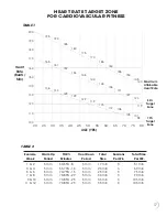
Page 18: ...0 min 9 10 5 min 70 85 25 5 min 35 min 3 105 min 11 12 5 min 70 85 25 5 min 35 min 3 105 min 17 HEART RATE TARGET ZONE FOR CARDIOVASCULAR FITNESS TABLE 1 Maximum Attainable Heart Rate 85 Target Zone 7...

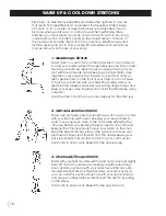
Page 19: ...when you feel the stretch Keep your kneecap pointing straight down and keep your knees close together Do not let the lifted knee swing outward Hold the stretch for 20 to 30 seconds Repeat for the othe...

Page 20: ...flat on the floor gently grasp the bent knee with your hands and pull it over your body and towards the ground You should feel a stretch in your hips abdominals and lower back Hold for 20 to 30 secon...

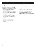
Page 21: ...s been carefully designed to require minimum maintenance However we recommend the following to keep your unit operating smoothly Unplug your unit when it is not in use Use your unit indoors only Wipe...

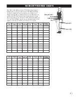
Page 22: ...a notebook You will find it both informative and motivational to look back at what you ve done and this data will help you to chart future fitness goals as you progress Every two weeks measure yourse...

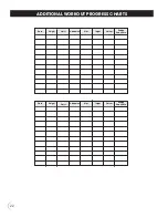
Page 23: ...22 Resting Heart Rate Calves Thighs Hips Abdomen Waist Weight Date Resting Heart Rate Calves Thighs Hips Abdomen Waist Weight Date ADDITIONAL WORKOUT PROGRESS CHARTS...

Page 24: ...____ ___________ ___________ ___________ Week Date Of Workouts Total Workout Time ___________ ___________ ___________ ___________ ___________ ___________ ___________ ___________ ___________ __________...

Page 25: ...__________ ___________ ___________ Week Date Of Workouts Total Workout Time ___________ ___________ ___________ ___________ ___________ ___________ ___________ ___________ ___________ ___________ ____...

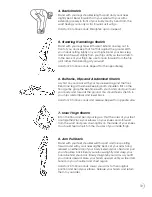
Page 26: ...If you have any comments or questions contact our Customer Service Department toll free at 1 800 292 5009 Monday through Friday 9 00am to 5 00pm EST Please record the following information and keep f...

Reviews: