4
4. External Dimensions and Nomenclature
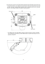
4-1. Main
Unit
Number Name
Description
1 Casing
cover
2 Casing
3
Sensor unit
Incorporates a gas sensor.
4
Sensor guard
Protects the sensor unit.
5
Ground terminal
Used when grounding the frame.
6
State display
indicator
Indicates the power supply state (green), alarm state (red), and trouble
state (yellow).
7
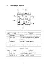
Control block
Insert the magnetic stick to control or set the product.
8
Display block
Displays the gas concentration and set values.
9
Cable entry
PF3/4orG3/4, pitch=1.81mm, Insertion length: 10.86mm,
No. of insertion threads: 6. Certified cable glands
*1
must be
provided by end user and used.
10
Hexagon socket
head cap screw
Used for securing the casing cover. Use a hexagon wrench with a
nominal diameter of 4 mm.
11
Hexagon socket
set screw
Used for securing the cable glands or sensor units. Use a hexagon
wrench with a nominal diameter of 2 mm.
*1: Used in ATEX hazardous, ATEX certified cable glands according to EN60079-0:2012 and
EN60079-1:2007.Used in IECEx hazardous area, IECEx certified cable glands according to
IEC60079-0:2011 and IEC60079-1:2007.
Summary of Contents for KD-12B
Page 43: ...40 ...


