Page | 7
Harness
A harness is available is designed to mate the logger with a CAN bus environment that utilizes a
Smartcraft connector on the CAN hub side.
Pin
Wire Color
Purpose
1
Violet
Key switch
2
Red
VBatt
3
Black
Ground
7
White
CAN H
8
Blue
CAN L
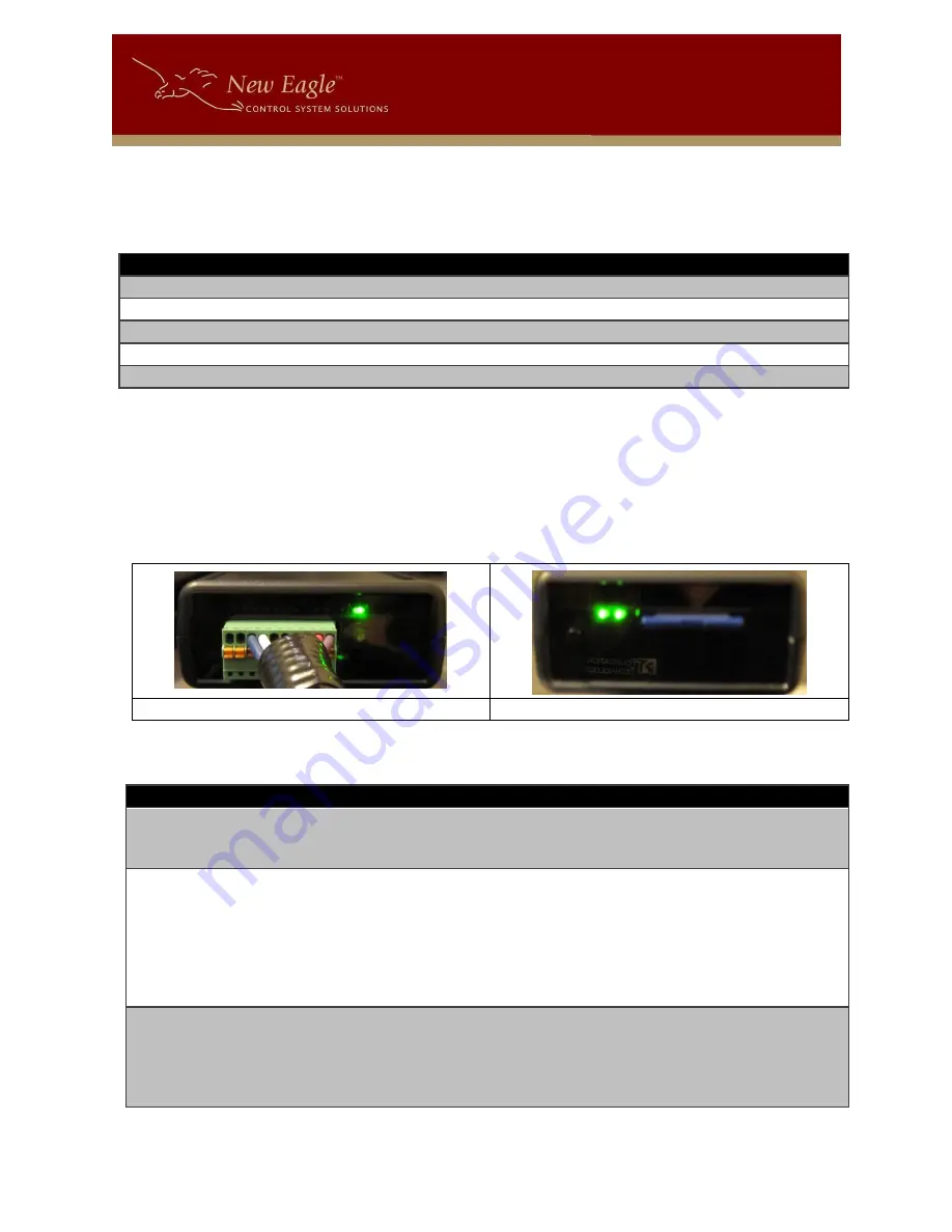
Logger Switches, LED’s and More….
The logger is equipped with Switches and more. There are two sides to the logger. One side contains
the connector for the harness, the reset button, and the state-of-health LED. The other side contains
the slot for the SD card, the User-Action button, and two more LEDS that provide indications for logging
and CAN bus activity.
LED’s
State-of-Health LED
File System and CAN Status LED’s
There are three LED’s, two on the SD Card slot side and one on the connecter side.
LED Location
Reference
Description
1
Connector Side
State-of-health
Blinking Green = Normal operation
Red = Error, unit must be reset
Blinking Orange = Shutting down
2
SD Side – closest
to SD
File System
Blinking Orange = Waiting for SD Card
Orange = SD Card detected
Green = System is ready to log
Blinking Green = data is being logged
Blinking Red = SD Card is write protected
Red = File System Error – SD card may be full or
needs to be replaced.
3
SD Side – closest
to User Action
Switch
CAN Status
Green = Ready
Blinking Green = CAN Data present
Blinking Orange = Waiting for data
Blinking Red = CAN bus is in error passive state
Red = Error, unit must be reset


