background image

2 of 12

SMB-189

SERVICE MANUAL BULLETIN 
SMB-189

The New Flyer vehicles described in this manual may be protected by one or more 
patents and design applications or registrations in the United States and Canada, 

and in other countries. Refer to “Vehicle Patent Information” in this manual.

Copyright © 2019 New Flyer Industries Canada ULC

PART ONE

1.

Lockout / Tagout Procedure 
for all Battery Electric 
Vehicles

The following Lock Out / Tag Out proce-
dure should be followed when working on
or near the High Voltage components.

NOTE:

Use commercially available lock out equip-
ment and tags and be sure to follow any
local laws or workplace procedures.

1.1.

Locking / Tagging Out

1. Set the Master Run switch to the STOP-

SYSTEM position.

2. Rotate the 12/24 volt Battery switch to the

OFF position.

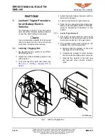
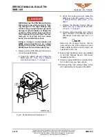
3. Lock and tag the switch and retain key.

See “Fig. 1: Locking / Tagging Out” on
page 2. 

4. Switch the High Voltage Interlock switch to

the HV OFF position.

5. Lock and tag the switch and retain key.

6. Verify the low voltage and high voltage sys-

tems are de-energized. Refer to De-Ener-
gizing & Energizing Procedures


in this

bulletin.

1.1.1.

Locks / Tags Removal

1. The locks and tags shall be removed by

the installer of the locks and tags or shall
be removed under her / his supervision.

2. If the installer of the locks and tags is not

available, then her/his supervisor:

a. Ensures that the installer of the locks

and tags is not in the facility.

b. Contacts the installer to inform her/him

that the locks and tags will be removed.

c. Reminds the installer of the lock and

tag removal when she/he resumes
work.

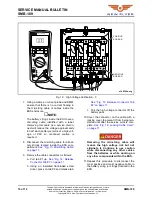
Fig. 1:   Locking / Tagging Out

+9

2))

s145303a.svg

Summary of Contents for Xcelsor 2019

Page 1: ...Industries Canada ULC ISSUE DATE Dec 20 2019 SMB 189 APPLICABILITY VEHICLE LENGTH 30ft 35ft 40ft 60ft ALL VEHICLE TYPE Xcelsior MiDi Invero ALL Low Floor High Floor FUEL TYPE Diesel Diesel Electric CNG LNG ALL Fuel Cell Trolley Electric Battery Electric SUBJECT High Voltage Safety Lockout Tagout De Energizing Energizing Procedure SECTION TITLE Lockout Tagout De Energizing Energizing Procedure DETA...

Page 2: ...SYSTEM position 2 Rotate the 12 24 volt Battery switch to the OFF position 3 Lock and tag the switch and retain key See Fig 1 Locking Tagging Out on page 2 4 Switch the High Voltage Interlock switch to the HV OFF position 5 Lock and tag the switch and retain key 6 Verify the low voltage and high voltage sys tems are de energized Refer to De Ener gizing Energizing Procedures in this bulletin 1 1 1 ...

Page 3: ...anual for information on how to safely prepare the work area 2 Ensure the DC high voltage charging cables are disconnected from the vehicle 3 Lock Out and Tag Out the Battery Discon nect and High Voltage Interlock switch Refer to 1 Lockout Tagout Procedure for all Battery Electric Vehicles on page 2 in this bulletin for procedure 4 Wear High Voltage Personal Protection Equipment PPE Refer to PPE R...

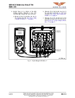
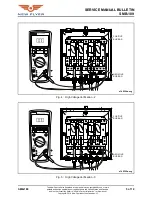
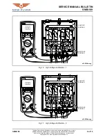
Page 4: ...ystem Measure in the roof mounted high voltage fuse box as follows a Measure from the positive bus bar to the negative bus bar See Fig 3 High Voltage Verification 1 on page 4 b Measure from the positive bus bar to the grounded enclosure or roof rack structure See Fig 4 High Voltage Ver ification 2 on page 5 c Measure from the ground bar to the grounded enclosure or roof rack struc ture See Fig 5 H...

Page 5: ... and in other countries Refer to Vehicle Patent Information in this manual Copyright 2019 New Flyer Industries Canada ULC Fig 4 High Voltage Verification 2 Fig 5 High Voltage Verification 3 2 9 9 168 7 21 168 7 21 7 67 168 7 21 08 7 0 7 5 9 168 7 21 9 7 9 7 P 86 1 7 9 86 5 326 7 9 86 5 s145304a svg 1 7 9 86 5 326 7 9 86 5 2 9 9 168 7 21 168 7 21 7 67 168 7 21 08 7 0 7 5 9 168 7 21 9 7 9 7 P 86 s14...

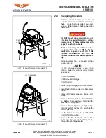
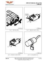
Page 6: ...al Service Disconnect plug 7 Remove all the ESS Manual Service Dis connect plugs as follows a Press the locking tab and rotate the MSD lever 45 See Fig 6 Manual Service Disconnect 1 on page 6 Fig 6 Manual Service Disconnect 1 b Press the locking tab and rotate the MSD lever to the 90 position See Fig 7 Manual Service Disconnect 2 on page 7 c Remove the Manual Service Discon nects See Fig 8 Manual ...

Page 7: ... While connecting HV cables continu ously monitor with the DMM for the inadvertent appearance of HV If HV appears troubleshoot why the HV appeared and resolve before proceed ing 1 Using insulated tools reconnect all high voltage cables NOTE For the following devices use a phase rotation meter to ensure correct cable sequences Air Compressor ESS Heat Exchanger HVAC Unit 2 Reinstall high voltage jun...

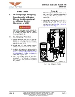
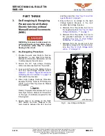
Page 8: ...out Tagout Procedure for all Battery Electric Vehicles on page 2 in this bulletin for procedure 4 Wear High Voltage Personal Protection Equipment PPE Refer to PPE Require ments in your New Flyer Service Manual for guidelines NOTE Refer to Equipment Requirements in your New Flyer Service Manual for information on the type of multimeter required for the following test 5 Ensure there is no voltage on...

Page 9: ...and in other countries Refer to Vehicle Patent Information in this manual Copyright 2019 New Flyer Industries Canada ULC Fig 10 High Voltage Verification 1 Fig 11 High Voltage Verification 2 2 9 9 168 7 21 168 7 21 7 67 168 7 21 08 7 0 7 5 9 168 7 21 9 7 9 7 P 86 1 7 9 86 5 326 7 9 86 5 s145302a svg 2 9 9 168 7 21 168 7 21 7 67 168 7 21 08 7 0 7 5 9 168 7 21 9 7 9 7 P 86 1 7 9 86 5 326 7 9 86 5 s1...

Page 10: ... tery strings located inside the ESS com partment See Fig 13 Mid String Cable on page 11 9 Remove the cable connectors as follows a Pull tab 1 up See Fig 14 Release Connector Tab 1 on page 11 b Using an insulated flat bladed screw driver press on tab 2 and release tab See Fig 15 Release Connector Tab 2 on page 11 c Pull the high voltage connector off the battery pack 10 Cover the connector on the ...

Page 11: ... or registrations in the United States and Canada and in other countries Refer to Vehicle Patent Information in this manual Copyright 2019 New Flyer Industries Canada ULC Fig 13 Mid String Cable Fig 14 Release Connector Tab 1 Fig 15 Release Connector Tab 2 Fig 16 Locking Cable Cover s145307a svg 7 7 s145309a svg 168 7 7 6 5 5 9 5 7 7 s145308a svg s145410a svg ...

Page 12: ...vehicle chassis While connecting HV cables continu ously monitor with the DMM for the inadvertent appearance of HV If HV appears troubleshoot why the HV appeared and resolve before proceed ing 1 Using insulated tools reconnect all high voltage cables NOTE For the following devices use a phase rotation meter to ensure correct cable sequences Air Compressor ESS Heat Exchanger HVAC Unit 2 Reinstall h...

Reviews:

Related manuals for Xcelsor 2019