MAINTENANCE
OM 0471MW-A
[26]
Figure 31
Figure 31b
Figure 31a
Belt Replacement
(figures 31-31a-31b)
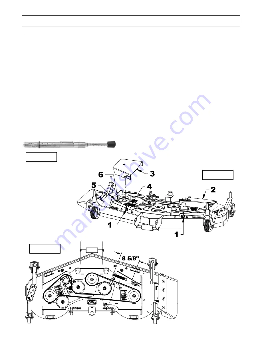
1. Figure 31:
Untighten the wing nut and
pivot the latch (item 1) lift the left and/or
right belt guards (item 2 and 3) at an
angle of 15° and pull them backward. Put
them aside for a future reinstallation.
2. Figure 31:
Remove the 3/8" hex nut (item
5) untighten the 3/8"NC nylon insert
locknut (item 6) to release the spring
(item 4).
3. Figure 31:
Remove the belt idler spring
(item 4).
4.
Replace the belt, by routing it through the
pulleys as shown on
Figure 31b
.
5.
Do the reverse step for reinstallation.
6.
The spring must be at 8 5/8" between the hooks
as shown in
Figure 31b
.
7.
According to the belt supplier use a belt tension
gauge
Figure 31a
. Apply between 12.3 and
13.1 pound of force for a deflection of .68”
(11/16”) on the longest section of a new belt.
(between the right and left spindle).
8. Figure 31:
If the tension is not as
recommended, untighten the 3/8” hex nut (item
5), slightly tighten the 3/8” nylon insert locknut
(item 6) every 1/8” check the tension with the
tension gauge. The length of the spring (item 4)
for a new belt should be around 8 5/8” between
the hooks. Tighten the 3/8” hex nut (item 5)
Summary of Contents for 266WMM
Page 9: ...GENERAL SAFETY INFORMATION OM 0471MW A 7 ...
Page 10: ...GENERAL SAFETY INFORMATION OM 0471MW A 8 1 Safety stand 2 Secure point for safety stand ...
Page 12: ...SAFETY LABELS OM 0471MW A 10 Replace immediately if damaged ...
Page 37: ...PARTS OM 0471MW A 35 UPPER PART OF MOWER FRAME ...
Page 39: ...PARTS OM 0471MW A 37 FRONT HITCH COMPONENTS ...
Page 41: ...PARTS OM 0471MW A 39 REAR HITCH COMPONENTS ...
Page 43: ...PARTS OM 0471MW A 41 DRIVE SYSTEM ...
Page 50: ......
Page 51: ... ...


