2-116
Issued 11-06
Bur
87519804 NA
CHAPTER 2 - 667TA ENGINE OVERHAUL
ENGINE REPAIR MANUAL
STEP 151
BS06K382
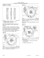
Figure 2-255
Check tappet adjusters (1) that they are loose to
prevent their balking on the rods (2, figure 2-254)
when installing the rocker assembly.
Then install the rocker assembly consisting of:
bracket (5), rockers (3), shafts (4), and secure them
to the cylinder head by tightening the fastening bolts
(2) to 36 Nm (26.5 lbf ft.) of specified torque.
LOCATING TOP DEAD CENTER (TDC)
IMPORTANT:
Due to the additional lobe for the
Internal EGR, each cylinder must cylinder must be
adjusted by taking it to the T.D.C. (top dead center)
and adjusting the clearance of both valves on every
cylinder.
STEP 152
BS06K345
Figure 2-256
•
Remove the injector from the number one cylinder.
•
Rotate engine over using Special Tool 380000988
to bring the number one cylinder to the highest
point using a dial indicator. Check to see if push
rods are loose, if they are not rotate the engine
360° now they should be loose.
•
Put a reference mark on tone wheel (1) and the
engine block (2).
STEP 153
Measure the circumference of the tone wheel and
divide by 3. Starting from the reference mark on tone
wheel put on in step 152. Put the other two marks of
the calculated length on the tone wheel.
VALVE CLEARANCE ADJUSTMENT
STEP 154
BS06K383
Figure 2-257
Adjust clearance between rockers and valves using
set screw wrench (1), box wrench (3) and feeler
gauge (2).
Working clearance shall be as follows:
•
Intake valves: 0.20 - 0.30 mm (0.008 - 0.012 in.)
•
Exhaust valves: 0.46 - 0.56 mm (0.18 - 0.022 in.)
NOTE:
Firing Order (1- 5- 3- 6- 2- 4)
•
Adjust the valves for cylinder number 1.
•
Rotate to the next reference mark and adjust valve
clearance for cylinder number 5.
•
Rotate to the next reference mark and adjust valve
clearance for cylinder number 3. This should be
one complete revolution of the tone wheel.
•
Rotate to the next reference mark and adjust valve
clearance for cylinder number 6.
•
Rotate to the next reference mark and adjust valve
clearance for cylinder number 2.
•
Rotate to the next reference mark and adjust valve
clearance for cylinder number 4. There should
have been two complete revolutions of the tone
wheel and all of the valves should be set.
•
Reinstall the number one injector.
1. ENGINE BLOCK
2. TONE WHEEL
1
2
3
4
5
2
1
1
3
2
Summary of Contents for 667TA/EBF
Page 4: ...SECTION 1 ENGINE REPAIR MANUAL II Issued 11 06 Bur 87519804 NA NOTES ...
Page 8: ...1 2 Issued 11 06 Bur 87519804 NA CHAPTER 1 DIAGNOSTICS ENGINE REPAIR MANUAL NOTES ...
Page 16: ...1 10 Issued 11 06 Bur 87519804 NA CHAPTER 1 DIAGNOSTICS ENGINE REPAIR MANUAL NOTES ...
Page 22: ...2 4 Issued 11 06 Bur 87519804 NA CHAPTER 2 667TA ENGINE OVERHAUL ENGINE REPAIR MANUAL NOTES ...
Page 144: ...3 2 Issued 11 06 Bur 87519804 NA CHAPTER 3 CHARGING AND START UP ENGINE REPAIR MANUAL NOTES ...
Page 150: ...3 8 Issued 11 06 Bur 87519804 NA CHAPTER 3 CHARGING AND START UP ENGINE REPAIR MANUAL NOTES ...


