background image

INTRODUCTION

Basic instructions - Fuse and relay locations

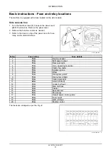
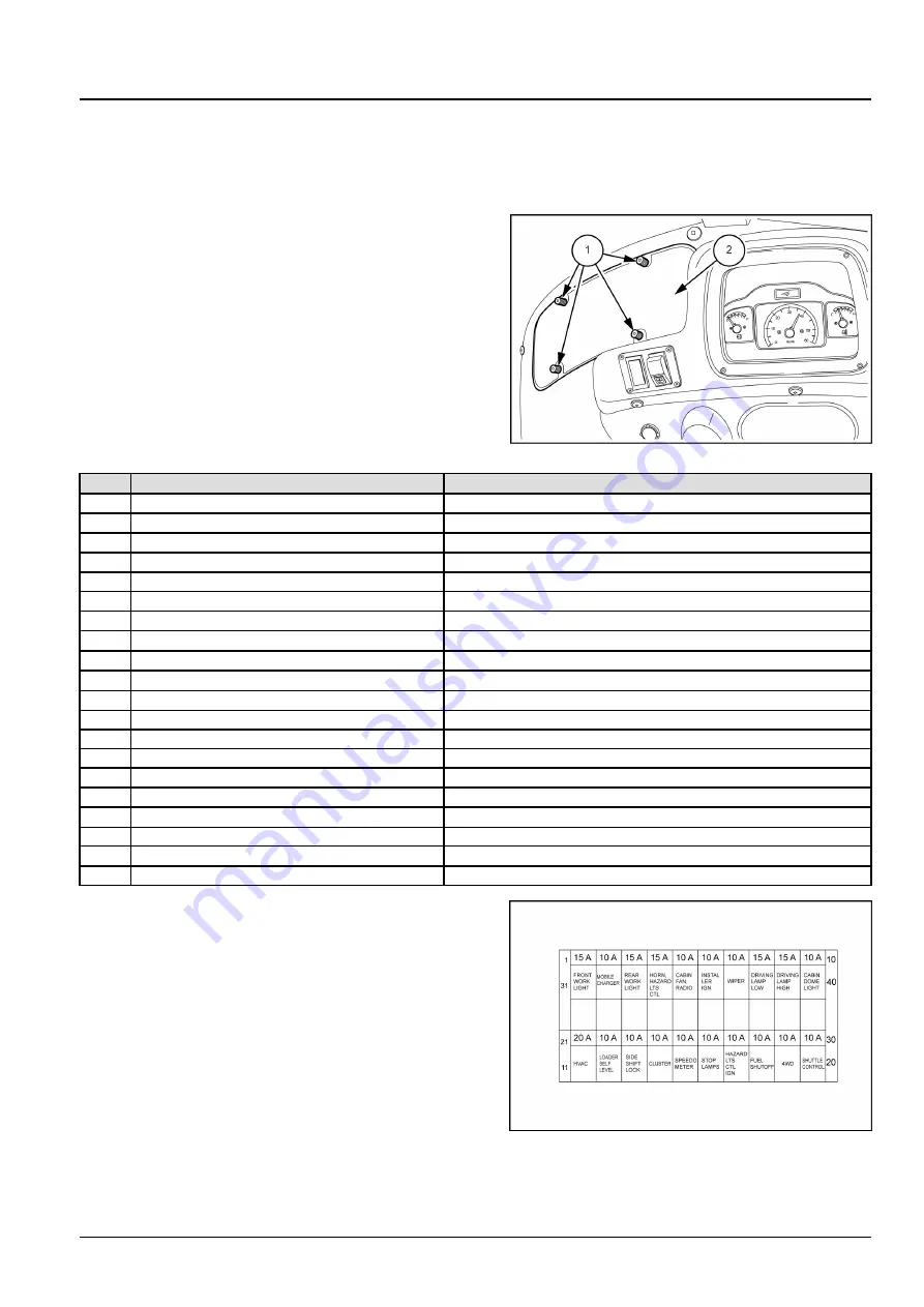
The machine is equipped with a fuse located on the side console.

Side console box

1. Turn the thumb screws

(1)

to loosen the panel cover

(2)

for the fuse box. Remove the panel cover.

2. Remove the fuse box covers as needed.

3. Refer to the decal on top of the panel cover for fuse,

relay, and/or diode functions.

PTIL17TLB0024AB

1

Sl No.

Fuse rating

Fuse details

1

15 A

Front work light

2

10 A

12 V

power output

3

15 A

Rear work light

4

15 A

Horn, hazard light control

5

10 A

Cabin, fan, radio

6

10 A

Installer ignition

7

10 A

Wiper

8

15 A

Driving lamp LOW

9

15 A

Driving lamp HIGH

10

10 A

Cabin dome light

11

20 A

HVAC (If fitted)

12

10 A

Loader self level

13

10 A

Side shift lock

14

10 A

Cluster

15

10 A

Speedometer

16

10 A

Stop lamps

17

10 A

Hazard lights control ignition

18

10 A

Fuel shutoff

19

10 A

4WD (If fitted)

20

10 A

Shuttle control

The fuses are arranged as per the Fig.

2

PTIL12TLB0441AA

2

48143704 20/04/2017

11

Summary of Contents for B80B

Page 1: ...SERVICE MANUAL B80B Backhoe Loader Part number 48143704 1st edition English April 2017 2017 Case New Holland Construction Equipment India Private Limited All Rights Reserved CONSTRUCTION...

Page 2: ...SERVICE MANUAL B80B 48143704 20 04 2017 EN Find manuals at https best manuals com...

Page 3: ...5 Front axle system 25 25 100 Powered front axle 25 1 25 102 Front bevel gear set and differential 25 2 25 108 Final drive hub steering knuckles and shafts 25 3 25 400 Non powered front axle 25 4 Rear...

Page 4: ...5 11 35 739 Swing arm hydraulic system 35 12 35 AAA Hydraulic systems generic sub group 35 13 Frames and ballasting 39 39 129 Stabilizers 39 1 Steering 41 41 101 Steering control 41 1 41 200 Hydraulic...

Page 5: ...114 Boom pivoting support 84 1 84 910 Boom 84 2 84 912 Dipper arm 84 3 Accessories 88 88 100 Accessories 88 1 Platform cab bodywork and decals 90 90 150 Cab 90 1 90 154 Cab doors and hatches 90 2 90...

Page 6: ...INTRODUCTION 48143704 20 04 2017 1 Find manuals at https best manuals com...

Page 7: ...tice regarding equipment servicing 9 Basic instructions 10 Basic instructions Fuse and relay locations 11 Basic instructions 12 Basic instructions 14 Basic instructions Shop and assembly 15 Torque Min...

Page 8: ...CAUTION indicates a hazardous situation that if not avoided could result in minor or moderate injury FAILURE TO FOLLOW DANGER WARNING AND CAUTION MESSAGES COULD RESULT IN DEATH OR SERIOUS INJURY Mach...

Page 9: ...nd filters must be disposed of in compliance with environmental standards and regulations Contact your Dealer with any questions regarding the service and maintenance of this machine Use this manual w...

Page 10: ...arts on this machine Before you weld cut or drill holes on any part of this machine make sure the part is not cast ductile iron See your dealer if you do not know if a part is cast ductile iron The fo...

Page 11: ...you weld cut or drill holes on any part of this machine make sure the part is not cast ductile iron See your dealer if you do not know if a part is cast ductile iron The following are cast ductile ir...

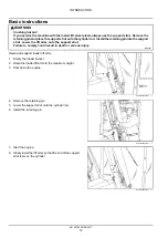
Page 12: ...for transport 3 Place the loader bucket on the ground with the bottom of the loader bucket parallel to the surface 4 Place the direction control lever and the transmission in neutral 5 If you need to...

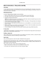
Page 13: ...spillage In general avoid skin contact with all fuels oils acids solvents etc Most of them contain substances that may be harmful to your health Modern oils contain additives Do not burn contaminated...

Page 14: ...y for damages caused by parts and or components not approved by the manufacturer including those used for the servicing or repair of the product manufactured or marketed by the manufacturer In any cas...

Page 15: ...roof goggles and protective clothing gloves and aprons Wash hands after handling Failure to comply could result in death or serious injury W0006A Do not run the engine with the alternator wires discon...

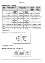
Page 16: ...Fuse rating Fuse details 1 15 A Front work light 2 10 A 12 V power output 3 15 A Rear work light 4 15 A Horn hazard light control 5 10 A Cabin fan radio 6 10 A Installer ignition 7 10 A Wiper 8 15 A D...

Page 17: ...upport strut Failure to comply could result in death or serious injury W0230A Raise and support loader lift arms 1 Empty the loader bucket 2 Raise the loader lift arms to the maximum height 3 Shut dow...

Page 18: ...longer rests on the cylinder 2 Shut down the engine RCPH10TLB227AAF 4 3 Remove the retaining pin from the support strut 4 Raise the support strut up to the storage position and secure with the retaini...

Page 19: ...release the hood latch PTIL13TLB1558AB 1 3 Lift the hood and rotate forward PTIL12TLB0559AB 2 NOTICE To avoid damage to the hood parts always close the hood before moving the loader Close the hood 1...

Page 20: ...Do not tap the seal with a hammer or mallet 6 While you insert the seal check that the seal is perpendicular to the seat When the seal settles make sure that the seal makes contact with the thrust ele...

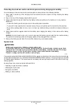
Page 21: ...cable from the machine battery The electronic monitoring system and charging system will be damaged if this is not done 5 Remove the battery ground cable Reconnect the cable when you complete welding...

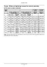
Page 22: ...n 25 N m 217 lb in 26 N m 234 lb in 35 N m 311 lb in 17 N m 151 lb in 24 N m 212 lb in M10 37 N m 27 lb ft 49 N m 36 lb ft 52 N m 38 lb ft 70 N m 51 lb ft 33 N m 25 lb ft 48 N m 35 lb ft M12 64 N m 47...

Page 23: ...N m 343 lb in 18 N m 163 lb in 27 N m 240 lb in M10 40 N m 30 lb ft 54 N m 40 lb ft 57 N m 42 lb ft 77 N m 56 lb ft 37 N m 27 lb ft 53 N m 39 lb ft M12 70 N m 52 lb ft 93 N m 69 lb ft 100 N m 74 lb f...

Page 24: ...t 7 16 48 N m 36 lb ft 65 N m 48 lb ft 68 N m 50 lb ft 91 N m 67 lb ft 50 N m 37 lb ft 71 N m 53 lb ft 1 2 74 N m 54 lb ft 98 N m 73 lb ft 104 N m 77 lb ft 139 N m 103 lb ft 76 N m 56 lb ft 108 N m 80...

Page 25: ...5 lb ft 153 N m 113 lb ft 74 N m 55 lb ft 104 N m 77 lb ft 9 16 117 N m 86 lb ft 156 N m 115 lb ft 165 N m 122 lb ft 221 N m 163 lb ft 106 N m 78 lb ft 157 N m 116 lb ft 5 8 162 N m 119 lb ft 216 N m...

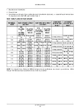
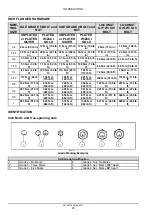
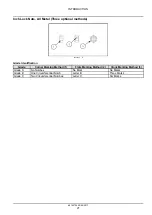
Page 26: ...4 Grade Identification Grade Corner Marking Method 1 Flats Marking Method 2 Clock Marking Method 3 Grade A No Notches No Mark No Marks Grade B One Circumferential Notch Letter B Three Marks Grade C T...

Page 27: ...15 lb ft 6 9 5 mm 3 8 in 9 16 18 29 33 N m 21 24 lb ft 20 27 N m 15 20 lb ft 8 12 7 mm 1 2 in 3 4 16 47 54 N m 35 40 lb ft 34 41 N m 25 30 lb ft 10 15 9 mm 5 8 in 7 8 14 72 79 N m 53 58 lb ft 47 54 N...

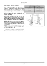
Page 28: ...CED FITTINGS When installing ORFS fittings thoroughly clean both flat surfaces of the fittings 1 and lubricate the O ring 2 with light oil Make sure both surfaces are aligned properly Torque the fitti...

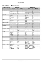
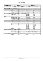
Page 29: ...d per inch lb in Frequency megahertz MHz megahertz MHz kilohertz kHz kilohertz kHz hertz Hz hertz Hz Frequency Rotational r min r min revolution per minute rpm revolution per minute rpm Length kilomet...

Page 30: ...foot per second ft s millimeter per second mm s inch per second in s meter per minute m min foot per minute ft min Volume includes Capacity cubic meter m cubic yard yd cu yd liter l cubic inch in lit...

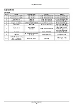
Page 31: ...LPOWER 9 00 l 2 38 US gal 5 Engine oil BS III API CI4 SAE 15W 40 Servo Pride Supreme 11 00 l 2 91 US gal 6 Brake fluid ISO 7308 Servo Transtrac HVI 0 67 l 0 18 US gal 7 Hydraulic oil ISO VG 68 IS 1052...

Page 32: ...SERVICE MANUAL Engine B80B 48143704 20 04 2017 10...

Page 33: ...Contents Engine 10 10 001 Engine and crankcase 10 1 10 254 Intake and exhaust manifolds and muffler 10 2 10 400 Engine cooling system 10 3 48143704 20 04 2017 10...

Page 34: ...Engine 10 Engine and crankcase 001 B80B 48143704 20 04 2017 10 1 10 001 1...

Page 35: ...Contents Engine 10 Engine and crankcase 001 SERVICE Engine Remove 3 Install 6 DIAGNOSTIC Engine Troubleshooting 9 48143704 20 04 2017 10 1 10 001 2...

Page 36: ...reference only ATTENTION Allow the engine to reach normal tempera ture before performing any service or maintenance proce dure Wear safety gloves and goggles for protection from hot components and fl...

Page 37: ...bly from the engine PTIL13TLB0958AB 4 6 Disconnect the throttle linkage 1 from the pump and set it aside PTIL13TLB0954AB 5 7 Disconnect the coolant temperature 1 alternator oil pressure 2 and starter...

Page 38: ...e the bolts 1 flat washers and nuts from the front engine mount Loosen and remove the cap screws and flat washers that fasten the transmission to the engine PTIL13TLB0730AB 8 Raise and remove the engi...

Page 39: ...ws to a torque of 52 57 N m 38 42 lb ft Install and tighten the front engine mounting bolts flat washers and nuts Tighten the self locking nuts to a torque of 90 100 N m 66 74 lb ft 3 Disconnect the l...

Page 40: ...by tightening the mounting bolts 2 PTIL13TLB0953AB 5 9 Connect the throttle rod 1 10 Connect the throttle cable from the mounting bracket 11 Connect the electrical connector for the oil pressure swit...

Page 41: ...ll the exhaust manifold Refer to Exhaust mani fold Install 10 254 17 Install the cooling pack Refer to Radiator Install 10 400 18 Fill the engine oil and cooling system up to the pre scribed level 19...

Page 42: ...ficient oil supply Check oil level and top up as necessary Overhaul or renew pump as necessary Check oil filter is not clogged Low oil pressure Overhaul pump or relief valve as necessary Excessive cra...

Page 43: ...water temperature gauge Renew temperature gauge Low oil pressure Engine oil level low Top up as necessary Wrong grade of oil Drain and refill with correct grade of oil Blocked oil pump sump screen Cl...

Page 44: ...Index Engine 10 Engine and crankcase 001 Engine Install 6 Engine Remove 3 Engine Troubleshooting 9 48143704 20 04 2017 10 1 10 001 11...

Page 45: ...48143704 20 04 2017 10 1 10 001 12...

Page 46: ...Engine 10 Intake and exhaust manifolds and muffler 254 B80B 48143704 20 04 2017 10 2 10 254 1...

Page 47: ...Contents Engine 10 Intake and exhaust manifolds and muffler 254 FUNCTIONAL DATA Exhaust manifold Exploded view 3 SERVICE Exhaust manifold Remove 5 Install 8 48143704 20 04 2017 10 2 10 254 2...

Page 48: ...manifolds and muffler Exhaust manifold Exploded view PTIL13TLB1200FB 1 1 Muffler 6 Bolt 2 Bracket with muffler 7 Washer 3 Screw 8 Muffler gasket 4 Washer 9 Muffler brace 5 Nylock nut 10 Nut 48143704...

Page 49: ...Engine Intake and exhaust manifolds and muffler PTIL13TLB1201FB 2 1 Exhaust stack 4 Washer 2 Clamp 5 Nylock nut 3 Bolt 48143704 20 04 2017 10 2 10 254 4...

Page 50: ...lock the support strut 1 to hold the loader Remove the battery cover and disconnect the negative battery cable from the battery and move it away from the battery terminal Refer to Basic instructions...

Page 51: ...This as a preview PDF file from best manuals com Download full PDF manual at best manuals com...


Reviews: