background image

Summary of Contents for LB110

Page 1: ...Backhoe Loaders LB75 B LB90 LB110 LB115 B SERVICE MANUAL II I EWHOLLAI CONSTRUCTION ...

Page 2: ...the illustrations do not necessarily show machines in standard condition For exact information about any particularmachine please consult yourNew Holland Construction Dealer PARTS AND ACCESSORIES Genuine parts and accessories have been specifically designed for these machines We would like to point out that non genuine parts and accessories have NOT been examined and released by the Company The in...

Page 3: ...he NewHolland Constructionoffice and provide themwith Your name address and telephone number Machine model and serial number Dealership name and address Machine purchase date and amount ofuse Nature ofproblem NEW HOLLAND CONSTRUCTION 245 E North Ave Carol Stream IL 60188 Ph 630 260 4000 When contactingNew Holland be aware thatyourproblemwill likelybe resolved inthe dealership using the dealer s fa...

Page 4: ...service You will be responsible for the cost oflubri cants fluids filters and other items replaced as part of normal maintenance Priorto taking the machine to your selling dealer for service it is recommended that you contactthem to determine any other charges for whichyou may be responsible All data given in this book is subjectto product variations Dimensions andweights are approximate only and ...

Page 5: ...S USED TOWARN OPERATORS AND OTHERS TO EXERCISE EVERY APPROPRIATE MEANS TO AVOID A SURPRISE INVOLVEMENT WITH MACHINERY DANGER THE WORD DANGER DENOTES A FORBIDDEN PRACTICE IN CONNEC TION WITH A SERIOUS HAZARD FAILURE TO FOLLOW THE CAUTION WARNING DANGER AND STOP IN STRUCTIONS MAY RESULT IN SERIOUS BODILY INJURY OR DEATH MACHINE SAFETY Additional precautionary statements ATTENTION and IMPORTANT are f...

Page 6: ...CAUSED BY FAILURE OF SOME INDIVIDUAL TO FOLLOW SIMPLE AND FUNDAMENTAL SAFETY RULES OR PRECAUTION FOR THIS REASON MOST ACCIDENTS CAN BE PREVENTED BY RECOGNIZING THE REAL CAUSE AND DOING SOMETHINGABOUT IT BEFOREACCIDENT OCCURS REGARDLESS OF THE CARE USED IN THE DESIGN AND CONSTRUCTION OF ANY TYPE OF EQUIPMENT THERE ARE MANY CONDITIONS THAT CAN T BE COMPLETELY SAFEGUARDED AGAINST WITHOUT INTERFERING ...

Page 7: ...65 WARNING Diesel engine exhaust and some of its constituents are know to the State of California to cause cancer birth defects and other reproductive harm 1999 NEW HOLLAND CONSTRUCTION Find manuals at https best manuals com ...

Page 8: ... 1 Fault Finding 11 Overhaul 18 CHAPTER 4 Fuel System DPS 203 Description Page Fuel System 1 Air Cleaner 13 Lift Pump 19 Injectors 23 Fuel Pump 31 CHAPTER 5 Turbocharger General Specifications 1 Fault Finding 5 Overhaul 8 Manifolds 15 CHAPTER 6 Lubrication System Description Page General Specifications 1 Fault Finding 4 Overhaul 5 CHAPTER 7 Cooling System Description Page General Specifications 1 ...

Page 9: ...ct Shuttle Description Page General Specifications 1 Description and Operation 5 Overhaul 28 CHAPTER 11 Powershift Introduction Description Page General Specifications 1 Description and Operation 2 Removal 35 CHAPTER 12 Powershift Operating Lever Description Page General Specifications 1 Fault Finding 14 CHAPTER 13 Powershift Overhaul includes 4 Wheel Steer Description Page General Specifications ...

Page 10: ...cription Page General Specifications 1 Overhaul 6 CHAPTER 17 Rear Axle with Electrically Operated Diff Lock 2 and 4 Wheel Drive Only Description Page General Specifications 1 Overhaul 8 CHAPTER 18 Rear Axle 4 Wheel Steer Only Description Page General Specifications 1 Overhaul 2 SECTION 33 BRAKE SYSTEMS CHAPTER 19 Brakes 2 and 4 Wheel Drive Only Description Page General Specifications 1 Overhaul 8 ...

Page 11: ...cations 2 Fault Finding 6 Pressure Testing 11 Flow Testing 21 CHAPTER 23 Hydraulic Circuits and Components REXROTH ONLY Description Page General Specifications 2 Hydraulic Circuits 9 Overhaul 31 CHAPTER 24 Fault Finding Pressure and Flow Testing Description Page Preliminary Checks 2 Fault Finding 3 Pressure Testing 7 Flow Testing 11 CHAPTER 25 Hydraulic Pump Description Page General Specifications...

Page 12: ...ral Specifications 1 Fault Finding 7 Overhaul 8 CHAPTER 29 Steering 4 Wheel Steer Only Description Page General Specifications 1 Fault Finding 7 Overhaul 1O SECTION 50 CAB HEATING AND AIR CONDITIONING CHAPTER 30 Cab Heating Description Page General Specifications 1 Fault Finding 5 Overhaul 6 CHAPTER 31 Air Conditioning Description Page General Specifications 1 Description operation 5 Fault Finding...

Page 13: ...CHAPTER 34 Starter Motor Description Page General Specifications 1 Fault Finding 4 Overhaul 8 CHAPTER 35 Alternator Description Page General Specifications 1 Fault Finding 4 Overhaul 9 CHAPTER 36 Battery Description Page General Specifications 1 Removal and Installation 2 Maintenance Testing 3 CHAPTER 37 Service Diagnostics Calibration and Immobiliser Description Page Service Indicator 1 Diagnosti...

Page 14: ...ications 2 Overhaul 5 SECTION 84 BACKHOE REMOVAL CHAPTER41 OVERHAUL Description Page General Specifications 1 Backhoe Control Linkage Overhaul 15 Component Removal 18 Extendible Dipperstick Overhaul 21 SECTION 88 DEALER KITS CHAPTER42 Description Page General 1 SECTION 90 CAB PARTS CHAPTER43 Description Page Description and Operation 3 Glass Replacement 11 Cab Trim 14 ...

Page 15: ...f the seal Coat the sealing lip with a thin layer of lubricant oil rather than grease and fill with grease the gap between the sealing lip and the dust lip of double lip seals Insert the seal into its seat and press it down using a flat punch Do no tap the seal with a hammer or a drift Take care to insert the seal perpendicularly to its seat while you are pressing it Once the seal is settled ensur...

Page 16: ...emind the Repair Personnel that having these equipment means work in optimal technical conditions obtain best results save time and effort work more safely NOTICES Wear limits indicated for some details should be intended as advised but not binding values The words front rear right hand and left hand referred to the different parts should be intended as seen from the operator s seat oriented to th...

Page 17: ...ng on the operator s seat except if they are certified operators to assist in the op eration to be carried out Never operate the machine or use attachments from a place other than sitting at the operator s seat Never carry out any operation on the machine when the engine is running except when specifi cally indicated LB 7 115 Stop the engine and ensure that all pressure is relieved from hydraulic ...

Page 18: ... wa ter or oil Do not pile up grease or oil soaked rags as they constitute a great fire hazard Always place them into a metal container Before starting the Machine or its attachments check adjust and block the operator s seat Also 604 56 061 00 09 2000 ensure that there are no persons within the Ma chine or attachment operating range Do not keep into your pockets any object which might fall unobse...

Page 19: ...ys take system pressure readings using the appropriate gauges WHEELS AND TIRES Check that the tiers are correctly inflated at the pressure specified by the manufacturer Periodi cally check possible damages to the rims and tires Keep off and stay at the tyre side when correcting the inflation pressure Check the pressure only when the Machine is un loaded and tires are cold to avoid wrong read ings ...

Page 20: ...in front of the right hand loader post in position 1 Example 000005017 VEHICLE IDENTIFICATION PLATE S 2 Figure 1 The machine identification plate s are located on the right hand loader post as shown at position 2 Re cord the data of your machine below MODEUTECHNICAL TYPE Example 699 510 700 UNIT SERIAL NO ExampIe 000005017 YEAR Example 1995 ENGINE IDENTIFICATION Figure 2 The engine identification ...

Page 21: ...he information below for quick reference MODEL NO Example COM T4 2025 SERIAL NO Example 15647 E95 01 TRANSMISSION P SHIFT Figure 5 The serial number and type is printed on the plate 1 on the lower right side of the transmission Record the information below for quick reference MODEL NO Example GT PRODUCTION SERIAL NO Example TBEA 419323 09 96 REAR AXLE IDENTIFICATION Figure 6 The serial number 1 is...

Page 22: ...re use and dis soil but should be collected and disposed of safe pose of these substances ly HELPFUL HINTS 1 Avoid filling tanks using jerry cans or inappropri ate pressurised fuel delivery systems which may cause considerable spillage 2 In general avoid skin contact with all fuels oils acids solvents etc Most of them contain sub stances which can be harmful to your health 3 Modern oils contain ad...

Page 23: ... components being served Connectors which show signs of movement from the original swagged position have failed and will ultimately sep arate completely LB 7 115 A hose with a chafed outer cover will allow water entry Concealed corrosion of the wire reinforcement will subsequently occur along the hose length with resultant hose failure Ballooning of the hose indicates an internal leakage due to st...

Page 24: ...Thread locking compound 82995773 HARDWARE TORQUE VALUES Check the tightness of hardware periodically Use the following charts to determine the correct torque when checking adjusting or replacing hard ware on the Backhoe Loader IMPORTANT DO NOT use the values listed in the charts if a different torque value or tightening pro 604 56 061 00 09 2000 TRADE DESCRIPTION LOCTITE GASKET ELIMINATOR 518 LOCT...

Page 25: ... 28 274 31 354 40 21 28 27 36 32 43 41 56 45 61 58 79 36 49 46 63 55 75 72 97 79 107 102 138 89 121 117 158 137 186 177 240 196 266 254 344 175 237 226 307 277 375 358 485 383 519 495 671 303 411 392 531 478 648 619 839 662 897 855 1160 NOTE Torque values shown with are inch pounds IDENTIFICATION HEX CAP SCREW AND CARRIAGE BOLTS CLASSES 5 6 AND UP MANUFACTURER S IDENTIFICATION AB CD PROPERTY CLASS...

Page 26: ...1 64 88 60 81 77 104 92 125 120 163 130 176 169 229 65 88 92 125 83 112 107 145 128 174 165 224 180 244 233 316 90 122 127 172 146 198 189 256 226 306 293 397 319 432 413 560 160 217 226 306 142 193 183 248 365 495 473 641 515 698 667 904 258 350 364 494 213 289 275 373 547 742 708 960 773 1048 1000 1356 386 523 545 739 NOMINAL SIZE 1 4 5 16 3 8 7 16 1 2 9 16 5 8 3 4 7 8 1 NOTE Torque values shown...

Page 27: ...pecifications for the various models NOTE All performance figures in this section are based on machines with standard buckets and will vary dependant upon the type of machine and any options that may be fitted Models LB75 B LB90 Refer to pages 11 to 22 Models LB110 Refer to pages 23 to 34 Models LB115 B Refer to pages 35 to 44 3 604 56 061 00 09 2000 ...

Page 28: ... CCMC D4 75 to 108 hp COOLING SYSTEM Ambra Agriflu 50 NH 900 A Antifreeze 75 to 108 hp Water 50 H2O 75 to 108 hp HYDRAULIC SYSTEM API GL4 ISO 32 46 Ambra Multi G 1 0W30 NH 410 B MIL L 2105 D 75 to 108 hp Hydrosystem Biodegradable NH 646 H BS 75 to 108 hp POWERSHUTTLE TRANS Ambra Multi G 1 0W30 NH 410 B API GL4 ISO 32 46 75 to 108 hp POWERSHIFT TRANS Ambra Hydrodex 3 NH 530 B ATF 75 to 108 hp FRONT...

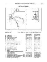
Page 29: ...g post L Center Line of rear axle to edge of backhoe bucket M Overall Length N Overall Height Lip of Bucket to top of Boom P Overall Width With Bucket P Overall Width Less Bucket Weight of machine Loader Backhoe example 4WD 6 in 1 Bucket Counterweights 4 2WD FRONT 11L 16SLF3 REAR 19 5 24 R4 4WD FRONT 12 16 5 REAR 19 5L 24 R4 2WD 4270mm 14ft 0in 4WD 4284mm 13ft 9in 2WD 3530 kg 7780 lbs 4WD 3560 kg ...

Page 30: ...ging Depth To Achieve a 0 6m 2ft Flat Bottom Trench 4234mm 13ft 11 in 5447mm 17ft 11in To Achieve a 2 4m 8ft Flat Bottom Trench 3854mm 12ft 8in 5160mm 16ft 11in J Maximum Digging Depth 4468mm 14ft 7in 5466mm 17ft 11 in K Stabilizer Spread Transport 2260mm 7ft 4in 2260mm 7ft 4in L Stabilizer Spread 3230mm 1 Oft in 3230mm 1 Oft in M Stabilizer Pad Levelling Angle 14 14 Swing Arc 180 180 Maximum digg...

Page 31: ...2930 2700 5955 1655 3655 2435 5370 1440 3175 2575 5680 1675 3700 2325 5125 1450 3195 2660 5870 1655 3655 2380 5245 1425 3145 3070 6770 1615 3565 2650 5850 1390 3070 5365 11830 1575 3475 3745 8265 1355 2990 1535 3390 5405 11920 1315 2905 1500 3310 1280 2830 1470 3240 1250 2760 1445 3190 1230 2710 1435 3170 1215 2680 1455 3205 1220 2695 1545 3410 1275 2875 1690 3725 1460 3220 I I I I I I A I I I I I...

Page 32: ...ged 355 Naturally Aspirated 262 Naturally Aspirated 445 Turbocharged 328 Turbocharged 0 36 0 46mm 0 014 0 018 in 0 43 0 53mm 0 017 0 021 in Type Pressurized Full Flow By pass with Expansion Chamber Fan Belt Deflection Naturally Aspirated Turbocharged Air Conditioning Compressor Thermostat Start to Open at Fully Open at Radiator Cap FUEL SYSTEM Injection Pump Type Cold Start Device Excess Fuel Devi...

Page 33: ...oe in 4WD REAR AXLE Type Differential Lock Power Shuttle Transmission Differential Lock Power Shift Transmission HYDRAULIC SYSTEM Twin Gear Pump Hydraulic System Pressure Main Relief Valve Pressure All Models Stabilizer Relief Valve Pressure All Models 70amp 12 volt Negative Earth 95 amp hr 12v 580A 900 CCA SAE on Negative chassis cable Transistorized Negative Positive Engagement Solenoid Operated...

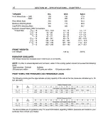
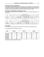
Page 34: ...hardness Chloride 300 parts per million Sulfates 100 parts per million 100 parts per million FRONT WHEEL TIRE PRESSURES AND PERMISSIBLE LOADS The following charts give the approximate carrying capacity of the axle at the tire pressures indicated up to 30 kph 20 mph Inflation Pressures in bar Tire Ply 1 5 1 7 1 9 2 1 2 2 2 4 2 6 2 8 3 0 3 3 3 6 3 9 size rating Permissible Load Capacity at the Axle ...

Page 35: ...8 R4 10 8380 8820 9260 10275 10540 10805 11220 11860 12480 12785 13465 21L 24 17 5L 24 10 7546 8228 8789 9152 9405 9966 10285 10516 10890 11440 11990 12342 12804 19 5 24 R4 10 8800 9360 10160 10400 11360 11680 12300 12800 13200 13600 14800 14800 15700 ROAD SPEEDS The following tables show the approximate ground speeds in km h and miles h at rated engine speed Naturally Aspirated Engine with Powers...

Page 36: ...10 SECTION 00 SPECIF CATIONS CHAPTER 2 NOTES ...

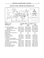
Page 37: ...Bucket Lip at ground level J Wheelbase K Center Line of rear axle to center line of swing post L Center Line of rear axle to edge of backhoe bucket M Overall Length N Overall Height Lip of Bucket to top of Boom P Overall Width With Bucket P Overall Width Less Bucket Weight of machine Loader Backhoe example 4WD 6 in 1 Bucket Counterweights 2WD 4270mm 14ft 0in 4WD 4284mm 13ft 9in 3530 kg 7780 lbs 63...

Page 38: ...6m 2ft Flat Bottom Trench 4562mm 14ft 11 in 5741mm 18ft 10in To Achieve a 2 4m 8ft Flat Bottom Trench 4214mm 13ft 1 0in 5468mm 18ft 0in J Maximum Digging Depth 4592mm 15ft 0in 5776mm 18ft 11 in K Stabilizer Spread Transport 2260mm 7ft 4in 2260mm 7ft 4in L Stabilizer Spread Working 3230mm 1 Oft in 3230mm 1 Oft in M Stabilizer Pad Levelling Angle 14 14 Swing Arc 180 180 Maximum digging force general...

Page 39: ...585 5705 1555 3430 2615 5770 1695 3735 2505 5520 1575 3470 2665 5880 1680 3710 2550 5625 1560 3440 2915 6425 1660 3665 2790 6155 1530 3375 3700 8155 1630 3590 3555 7840 1495 3300 6080 13410 1600 3525 5910 13038 1460 3225 1570 3460 1430 3155 1545 3410 1400 3090 1530 3370 1380 3045 1525 3360 1370 3025 1540 3400 1380 3045 1610 3550 1435 3170 1920 4230 1710 3770 I I I I I I A I I I I I _ SH84004 B HED...

Page 40: ...ction Naturally Aspirated Turbocharged Air Conditioning Compressor Thermostat Start to Open at Fully Open at Radiator Cap FUEL SYSTEM Injection Pump Type Cold Start Device Excess Fuel Device Fuel Shut Off Lift Pump Injectors TRANSMISSION 13 19mm 0 50 0 75 in 10 16mm 0 38 0 62 in Tensioner 82 C 180 F 95 C 203 F 0 90 bar 13 lb in2 Lucas DPS 203 Rotary Turbocharged Thermostart Automatic Governor Sole...

Page 41: ...Shift Transmission HYDRAULIC SYSTEM Twin Gear Pump Hydraulic System Pressure Main Relief Valve Pressure All Models Stabilizer Relief Valve Pressure All Models Negative Positive Engagement Solenoid Operated 3 1 kw 55 60W H4 Halogen 5 21 W Bayonet Cap 1OW Festoon and 1OW Bayonet Cap 21W Bayonet Cap 55W H3 Halogen 1 2W Capless 1 2W Capless Wet Multi Discs x8 per Axle x4 per half Axle 203 2mm 8 in Sin...

Page 42: ...fates 100 parts per million 100 parts per million FRONT WHEEL TIRE PRESSURES AND PERMISSIBLE LOADS The following charts give the approximate carrying capacity of the axle at the tire pressures indicated up to 30 kph 20 mph Inflation Pressures in Bar Tire Ply 1 5 I 1 7 I 1 9 I 2 1 I 2 2 I 2 4 I 2 6 I 2 8 I 3 0 I 3 3 I 3 6 I 3 9 size rating Permissible Load Capacity at the Axle kg 11L 16 10 1400 1 1...

Page 43: ... 3250 21L 24 2800 3000 3150 3350 3550 3650 19 5 24 R4 10 3990 4245 4610 4220 5150 5300 5580 5805 5990 6170 6710 6710 7120 Inflation Pressures in lbf ln2 Tire Ply 16 size rating 17 19 20 22 23 25 26 28 29 32 33 35 38 Permissible Load Capacity Per Axle lb 21L 24 6150 6600 7400 7850 8550 16 9 28 4169 6105 5258 5984 6226 19 5L 24 R4 10 8800 9360 10160 10400 11360 11680 12300 12800 13200 13600 14800 14...

Page 44: ...18 SECTION 00 SPECIF CATIONS CHAPTER 2 NOTES ...

Page 45: ...back at ground level 45 45 45 E Dump Angle 45 45 45 F Reach fully raised 744mm 2ft 4in 744mm 2ft 4in 744mm 2ft 4in G Height to Top Of Cab 2900mm 9ft 4in 2900mm 9ft 4in 2900mm 9ft 4in H Peel Depth 113mm 4ft 4in 113mm 4ft 4in 113mm 4ft 4in I Center line of axle to Bucket Lip 1975mm 6ft 4in 1975mm 6ft 4in 1975mm 6ft 4in I Center line of axle to Lift Fork Tip at ground level 1 375 m 4 5 ft J Wheelbase...

Page 46: ...c Maximum digging force crowd cylinder bucket cylinder Lift capacity through dipper arc Lift capacity dipper 121 m above ground Lift capacity at 41 above ground Extendible dipper extension length Standard Dipper Extendible Dipper 1956mm 6ft 3in 2902mm 9ft 4in 204 204 5711mm 18ft 6in 6371 mm 20ft 1in 3908mm 12ft 10in 4628mm 15ft 2in 5849mm 19ft 3in 6927mm 22ft 9in 6963mm 22ft 10in 7925mm 26ft 0in 6...

Page 47: ... 2425 5610 1510 3330 2560 5645 1660 3660 2450 5400 1540 3395 2620 5775 1660 3660 2505 5525 1535 3385 2875 6340 1645 3625 2750 6065 1515 3340 3700 8155 1620 3570 3550 7825 1490 3285 6280 13845 1600 3525 6075 13395 1460 3220 1575 3475 1435 3165 1555 3430 1410 3110 1545 3405 1400 3085 1550 3415 1395 3075 1580 3485 1415 3120 1670 3680 1500 3305 2070 4565 1855 4090 I I I I I I A I I I I I B SH84004 HED...

Page 48: ...tioning Compressor Thermostat Start to Open at Fully Open at Radiator Cap FUEL SYSTEM Injection Pump Type Cold Start Device Excess Fuel Device Fuel Shut Off Lift Pump Timing Injectors TRANSMISSION Tensioner 82 C 180 F 95 C 203 F 0 90 bar 13 lb in2 Lucas DPS 203 Rotary Turbocharged Thermostart Automatic Governor Solenoid Electric 28 3 T D C Turbocharged LO 67PP Turbocharged POWER SHIFT 4X2 4 Forwar...

Page 49: ...00 590 Backhoe Attaching Bolts 970 715 Cab ROPS Attaching Bolts 380 280 Turbocharger 20 15 Oil Outlet Pipe 34 25 Hydraulic Hoses Tubes ORS Connections Thread Size 9 16 18 11 15 16 13 15 16 1 14 13 15 12 17 15 12 111 15 12 2 12 1OW Festoon and 1OW Bayonet Cap 21W Bayonet Cap 55W H3 Halogen 1 2W Capless 1 2W Capless Wet Multi Discs 4 per Axle 203 2mm 8 in Single Disc on Driveline Hydrostatic 3 1 3 0...

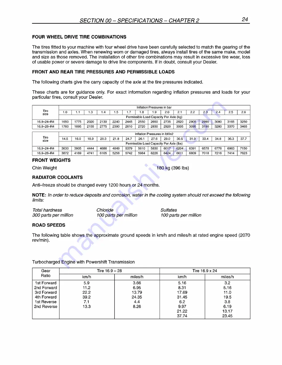
Page 50: ...5 I 2775 I 2390 I 2610 I 2720 I 2830 I 2920 I 3005 I 3095 I 3190 I 3280 I 3370 I 3465 Inflation Pressures in lbf in2 Tire 14 5 I 16 0 I 18 9 I 20 3 I 21 8 I 24 7 I 26 1 I 27 6 I 29 o I 30 5 I 31 9 I 33 4 I 34 8 I 36 3 I 37 7 size Permissible Load Capacity Per Axle lbs 16 9 24 R4 3530 I 3905 I 4444 I 4686 I 4849 I 5379 I 5610 I 5830 I 6017 I 6204 I 5391 I 6578 I 6776 I 6963 I 7150 16 9 28 R4 3872 I...

Page 51: ...This as a preview PDF file from best manuals com Download full PDF manual at best manuals com ...


Reviews:

Related manuals for LB110