background image

SECTION 00 - GENERAL INFORMATION

00-16

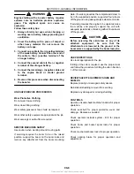
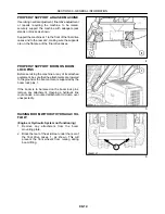
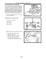
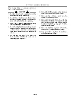
RAISING BOOM WITHOUT BATTERY
VOLTAGE (12 VOLTS)

1. Remove any attachment from the boom

mounting plate.

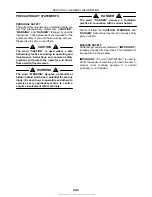
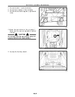
2. Block the rear of the skid steer under the rear of

the final drive cases, 1, as shown. This will
prevent the front wheels from raising during
boom lifting.

19995757

1

 9

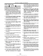
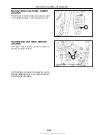
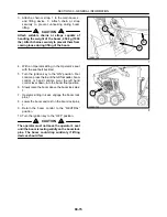
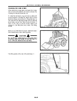
3. Attach a chain or strap, 1, to the main boom, 2,

and lifting device, 3. Attach chain or strap
securely to prevent unhooking during boom
lifting.

CAUTION

Attach suitable chains or straps capable of
handling the weight of the boom, 454 kg (1000
lbs). Attach chains securely to prevent them from
coming loose during lifting of the boom.

3

19995758

2

1

 10

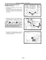
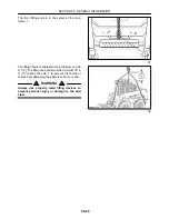
4. Remove the rod end (top) pivot pins, 1, from both

cylinders by removing the retaining hardware, 2,
from pivot pin and boom.

19995760

2

1

 11

Summary of Contents for LS160

Page 1: ...E C N A M R O F R E P N E V O R P Workshop Manual Workshop Manual 7 0 6 3 1 4 0 6 No Print y l a t I n i d e t n i r P English LS160 LS170 LS160 LS170...

Page 2: ...n Straight Thread O Ring Bosses 00 12 Standard Torque Data for Hydraulic Tubes and Fittings 00 12 Pipe Thread Fitting Torque 00 13 Lubricants and Coolants 00 13 Sealants 00 13 Properly Support a Raise...

Page 3: ...nstructions in this manual Your New Holland dealer is interested in your obtaining the most from your investment and will be glad to answer any questions you may have about your skid steer When major...

Page 4: ...ly designed for HEW HOLLAND MACHINES We would like to point out that NON GENUINE parts and accessories have not been examined and released by NEW HOLLAND The installation and or use of such products c...

Page 5: ...rd WARNING denotes a potential or hidden hazard which has a potential for serious injury It is used to warn operators and others to exercise every appropriate means to avoid a surprise involvement wit...

Page 6: ...ct the negative ground battery cable This will shut off power to the eic and prevent damage to the eic board or blowing the 5 amp fuses if the board is accidentally grounded 16 If welding is required...

Page 7: ...ea that may hinder safe machine operation 40 Never operate the skid steer with any of the shielding removed 41 Never operate the skid steer without windows and or screens in place 42 Never extend any...

Page 8: ...gangrene may result Doctors unfamiliar with this type of injury should reference a knowledgeable medical source AVOID HEATING NEAR PRESSURIZED FLUID LINES Flammable spray can be generated by heating...

Page 9: ...port the boom on the boom locks and remove any attachment from the boom mounting plate If servicing requires the complete skid steer to be in the supported position support all four wheels off the gro...

Page 10: ...the operator s cab at 1 2534 05 1 1 ENGINE MODEL AND SERIAL NUMBER LOCATION The engine model and serial number is located on the left side of the block at 1 4800 11 1 1 2 For the tightening torques fo...

Page 11: ...5 13 149 17 178 20 229 26 250 28 324 37 125 14 176 20 5 16 1 4 55 6 2 72 8 1 86 9 7 112 13 121 14 157 18 61 6 9 86 9 8 1 4 MINIMUM HARDWARE TIGHTENING TORQUES IN FOOT POUNDS NEWTON METERS FOR NORMAL A...

Page 12: ...71 195 265 M24 303 411 392 531 478 648 619 839 662 897 855 1160 338 458 NOTE Torque values shown with are inch pounds IDENTIFICATION HEX CAP SCREW AND CARRIAGE BOLTS CLASSES 5 6 AND UP MANUFACTURER S...

Page 13: ...5 12 15 24 40 53 82 100 120 150 175 240 16 20 33 54 79 111 136 163 204 237 325 12 16 29 47 72 104 122 149 190 217 305 NEWTON METERS 6 4 7 9 9 5 12 7 15 9 19 1 22 2 25 4 31 8 38 1 50 8 mm 4 5 6 8 10 12...

Page 14: ...L 9613360 API Service SH CG4 10W 30 All lubrication fittings Tube 9613310 High viscosity lithium base grease Engine 1 qt 9613313 2 5 gal 9613314 1 L 9613358 20 L 9613360 API Service SH CG4 10W 30 Refe...

Page 15: ...PINS Before servicing the machine or any of its attached equipment be sure that the attachments are lowered to the ground or the boom arms are supported by the boom lock pins 1 If the boom is to be ra...

Page 16: ...belt buckled 5 Turn the ignition key to the ON position Foot controls press the toe of the left foot pedal boom control or hand controls pivot the left hand control lever down into the boom float pos...

Page 17: ...19995757 1 9 3 Attach a chain or strap 1 to the main boom 2 and lifting device 3 Attach chain or strap securely to prevent unhooking during boom lifting CAUTION Attach suitable chains or straps capabl...

Page 18: ...es the boom lock pins 1 8 Lower the boom and rest on the boom lock pins 1 CAUTION The operator must not leave the operator s seat until the boom is resting solidly on the boom lock pins The boom could...

Page 19: ...linder rod to align cylinder with pivot pin Stop engine 7 If cylinder and boom are not properly aligned sit in the operator s seat with seat buckled turn the ignition key to the ON position Move the b...

Page 20: ...jor service or repairs of the skid steer Using the proper cab tilting tool and following these steps the cab and boom can be tilted forward 1 Remove any attachment bucket etc from the boom quick attac...

Page 21: ...f the final drive housings and the rear blocks 2 to the rear of the flat area of the final drive housings WARNING Never attempt to tilt the skid steer cab over unless the skid steer is securely suppor...

Page 22: ...sides 9 Remove the rear fender supports 3 right and left sides 23 10 Raise the seat and lock in the up position 1 Make sure the seat pan assembly is latched securely CAUTION Do not work under the seat...

Page 23: ...left final drive housing and attach with a 1 2 x 8 cap screw two spacers one each side of housing at 2 and 1 2 nut 27 14 Install the upper cab jack support 1 The spacer channel 2 is used for the LS160...

Page 24: ...er loosen or remove any cab retaining hardware before the jack assembly is installed 29 18 Jack cab and boom assembly over with the skid steer properly supported off the ground Support the boom at 1 t...

Page 25: ...ic control handles 31 6 Reinstall all cab support bolts front and rear Torque the rear bolts 1 to 108 N m 80 ft lbs Make sure the spacers are reinstalled NOTE If spacers were installed under the rear...

Page 26: ...being craned Refer to Specifications in this manual for the operating weight of the model skid steer being craned Use three chains minimum of 3 66 m 12 long to prevent sharp angles and damage to the s...

Page 27: ...lifting chains or cables must be minimum of 3 66 m 12 The lifting hook point must be minimum of 1 9 m 75 above the cab 1 to prevent the chains or cables from damaging the skid steer frame or cab WARN...

Page 28: ...on the skid steer main frame to insure they are in good condition If worn or damaged do not use 5 Do not lift the skid steer with any frame mounted attachments such as a backhoe or rear stabilizers 6...

Page 29: ...st adapter NH00117 OTC Oil pump port block installer NH11097 OTC Oil pump port block remover Hydraulic System Tool Number Order From Description LS160 LS170 238 Bar 3500 PSI Test Gauge OTC Main system...

Page 30: ...8 in Exhaust cold 0 2 mm 0 008 in FIRING ORDER 1 3 4 2 FUEL CONSUMPTION approximate at continuous full load 9 5 LPH 2 5 GPH IGNITION TYPE Compression GRADEABILITY Intermittent duty 30 Degrees All Dire...

Page 31: ...M 3155 RPM 2300 PSI Hydraulic system Capacity 32 6 L 8 6 gal Hydraulic Fluid SAE 10W 30 API SH CG4 Control Valve 3 Spool Open Center Main system relief 170 177 bar 2500 2600 PSI Circuit relief boom 23...

Page 32: ...6 5 HD 2000 345 kPa 50 PSI 10 00 16 5 HST HOLLOW SEGMENTED N A 31 15 5 15 G1 Flotation 276 kPA 40 PSI BASIC WEIGHT With 157 cm 66 Dirt Foundry bucket 79 kg 175 lb operator full fuel tank battery and 1...

Page 33: ...0 2 mm 0 008 in Exhaust cold 0 2 mm 0 008 in FIRING ORDER 1 3 4 2 FUEL CONSUMPTION approximate at continuous full load 12 1 LPH 3 2 GPH IGNITION TYPE Compression GRADEABILITY Intermittent duty 30 Deg...

Page 34: ...M 3155 RPM 2300 PSI Hydraulic system Capacity 32 6 L 8 6 gal Hydraulic Fluid SAE 10W 30 API SH CG4 Control Valve 3 Spool Open Center Main system relief 170 177 bar 2500 2600 PSI Circuit relief boom 23...

Page 35: ...6 5 HD 2000 345 kPa 50 PSI 10 00 16 5 HST HOLLOW SEGMENTED N A 31 15 5 15 G1 Flotation 276 kPA 40 PSI BASIC WEIGHT With 157 cm 66 Dirt Foundry bucket 79 kg 175 lb operator full fuel tank battery and 1...

Page 36: ...S170 WITH 66 DIRT AND FOUNDRY BUCKET AND 10 X 16 5 TIRES CM IN 1 OVERALL WIDTH w BUCKET 166 6 cm 65 6 2 TURNING RADIUS FRONT 189 2 cm 74 3 TURNING RADIUS REAR 152 4 cm 60 4 WHEEL TREAD w 10 X 16 5 TIR...

Page 37: ...29 6 cm 90 4 4 DUMP ANGLE MAX 46 5 ROLLBACK FULLY RAISED 83 6 BOOM REACH TO PIVOT PIN At max reach 37 0 cm 14 56 7 DUMP REACH MAXIMUM HEIGHT 70 5 cm 27 75 8 OVERALL HEIGHT 189 9 cm 74 75 9 ANGLE OF DE...

Page 38: ...ical Diagram 10 22 10 001 10 Engine Removal 10 23 10 001 53 Engine Disassembly Sequence 10 28 Engine Component Maintenance 10 36 10 101 55 Valve Seat 10 39 10 101 56 Cylinder Block 10 41 10 105 22 Pis...

Page 39: ...50 Reinstallation of Engine into Skid Steer Frame 10 75 How to Operate the Engine After Overhaul 10 77 Cooling System 10 78 Cooling System Operation 10 78 Water Pump Assembly and Thermostat Housing 10...

Page 40: ...ellent start ability 19992590 1 ENGINE COMPONENT DESCRIPTIONS CYLINDER BLOCK The cylinder block is made from high grade cast iron with copper and chrome additives and is integral with the crankcase Th...

Page 41: ...This as a preview PDF file from best manuals com Download full PDF manual at best manuals com...

Reviews:

Related manuals for LS160