background image

This as a preview PDF file from 

best-manuals.com

Download full PDF manual at  

best-manuals.com

Summary of Contents for TK4020F

Page 1: ...40 TK4040M TK4050 TK4050M TK4060 Tractor Part number 47830952 English February 2015 2015 CNH Industrial Italia S p A All Rights Reserved SERVICE MANUAL 1 1 Part number 47830952 TK4020F TK4020V TK4030 TK4030F TK4030V TK4040 TK4040M TK4050 TK4050M TK4060 Tractor ...

Page 2: ...SERVICE MANUAL TK4020F TK4020V TK4030F TK4030V TK4030 TK4040M TK4040 TK4050M TK4050 TK4060 47830952 26 03 2015 EN Find manuals at https best manuals com ...

Page 3: ...K4030V Middle East Africa F5AE9484B TK4030V Europe F5AE9484B TK4030V Australia New Zealand F5AE9484B TK4040 Middle East Africa F5AE9484G TK4040 Australia New Zealand F5AE9484G TK4040 Europe F5AE9484G TK4040 Asia Pacific F5AE9484G TK4040M Europe F5AE9484G TK4040M Asia Pacific F5AE9484G TK4040M Australia New Zealand F5AE9484G TK4040M Middle East Africa F5AE9484G TK4050 Europe F4CE9487N TK4050 Austra...

Page 4: ...ve 21 2 21 140 Mechanical transmission internal components 21 3 21 148 Transmission Rear drive internal components 21 4 21 160 Creeper 21 5 21 162 Reverser 21 6 Rear axle system 27 27 100 Powered rear axle 27 1 27 126 Spur gear and final drives 27 2 Power Take Off PTO 31 31 114 Two speed rear Power Take Off PTO 31 1 Brakes and controls 33 33 120 Mechanical service brakes 33 1 33 202 Hydraulic serv...

Page 5: ... suspension 48 4 48 134 Track tension units 48 5 48 138 Track rollers 48 6 Electrical systems 55 55 100 Harnesses and connectors 55 1 55 201 Engine starting system 55 2 55 301 Alternator 55 3 55 302 Battery 55 4 55 640 Electronic modules 55 5 55 404 External lighting 55 6 55 408 Warning indicators alarms and instruments 55 7 55 DTC FAULT CODES 55 8 Platform cab bodywork and decals 90 90 150 Cab 90...

Page 6: ...INTRODUCTION 47830952 26 03 2015 1 Find manuals at https best manuals com ...

Page 7: ...Contents INTRODUCTION Safety rules 3 Basic instructions 7 Consumables 10 47830952 26 03 2015 2 Find manuals at https best manuals com ...

Page 8: ...ar antee against accidents Precise observance of the most basic safety rule is nor mally sufficient to avoid many serious accidents DANGER Never carry out any cleaning lubrication or maintenance operations when the engine is running Safety regulations General guidelines Carefully follow specified repair and maintenance procedures Do not wear rings wristwatches jewellery unbuttoned or loose article...

Page 9: ...n toxic commercially available solvents Wear safety goggles with side guards when cleaning parts with compressed air Limit the air pressure to a maximum of 2 1 bar according to local regulations Do not run the engine in confined spaces without suitable ventilation Do not smoke use naked flames or cause sparks in the area when fuel filling or handling highly inflammable liquids Never use naked flam...

Page 10: ...ing leave the battery compartment uncovered to improve ventilation Never check the battery charge using jumpers metal objects placed on the terminals Avoid sparks or flames near the battery zone Do not smoke to prevent explosion hazards Before servicing operations check for fuel or current leaks eliminate any eventual leaks before proceeding with work Do not charge batteries in confined spaces mak...

Page 11: ... using inflammable gases as this may result in explosions and injury to bystanders Removal and re fitting Lift and handle all heavy parts using suitable hoisting equipment Make sure that parts are sustained by appropriate hooks and slings Use the hoisting eyebolts for lifting operations Extra care should be taken if persons are present near the load to be lifted Handle all parts with carefully Do ...

Page 12: ...fluid with hydrodynamic lips take into consideration the shaft rotation direction and position the grooves so that they will deviate the fluid towards the inner side of the seal Smear the sealing lip with a thin layer of lubricant use oil rather than grease and fill the gap between the sealing lip and the dust lip on double lip seals with grease Insert the seal in its seat and press down using a f...

Page 13: ...ate any sharp edges or burr and carefully clean the seats for the rubber rings 2 Thoroughly clean the rings on the seals 3 Insert each metal ring 2 on the respective rubber ring 1 as shown in the drawing acting on the points in dicated by the arrows MOLI11K0001AB 1 4 Make sure that the metal ring is fitted correctly check ing that measurement A is constant on all of the cir cumference 5 Assemble e...

Page 14: ... benefit from Operating in optimal technical conditions Obtaining the best results Saving time and effort Working in safe conditions Important notes Wear limit values indicated for certain parts are recommended but not binding The terms front rear right hand and left hand when referred to different parts are intended as seen from the driving position with the tractor in the normal direction of mov...

Page 15: ... l min TK4050 TK4060 9 5 l min NEW HOLLAND AMBRA MASTERGOLD HSP ENGINE OIL NH 330G SAE 15W40 NH 324G SAE 10W30 API CI 4 CH 4 ACEA E7 E5 Servo control for central clutch version on request 0 8 l min NEW HOLLAND AMBRA SHIFTSPEED NH 622HV SAE 75W Steering clutches 1 4 l min NEW HOLLAND AMBRA SUPER 10 W NH 301C API CE MIL L 2104E SAE 10W Transmission gearbox bevel drive brakes and hydraulic lift TK402...

Page 16: ...SERVICE MANUAL Engine TK4020F TK4020V TK4030F TK4030V TK4030 TK4040M TK4040 TK4050M TK4050 TK4060 47830952 26 03 2015 10 ...

Page 17: ...Contents Engine 10 10 001 Engine and crankcase 10 1 10 216 Fuel tanks 10 2 10 400 Engine cooling system 10 3 47830952 26 03 2015 10 ...

Page 18: ...Engine 10 Engine and crankcase 001 TK4020F TK4020V TK4030F TK4030V TK4030 TK4040M TK4040 TK4050M TK4050 TK4060 47830952 26 03 2015 10 1 10 001 1 ...

Page 19: ...Contents Engine 10 Engine and crankcase 001 SERVICE Engine Remove 3 Install 7 47830952 26 03 2015 10 1 10 001 2 ...

Page 20: ...f the elements between the two engines NEF and F5A keep in mind that the gears of the timing system are respectively on the flywheel side for the former and on the fan side for the latter The removal operations are similar for both engines A note shows the differences between the two engines Perform operations Clutch Remove 18 110 Then proceed as follows 1 Remove the right hand 1 and left hand sup...

Page 21: ...ction pump looking at the machine from the same side is on the left and the prim ing pump is on the right MOLI11K0013AB 5 6 For models TK4050 and TK4060 Detach the flow and return pipes 1 from the heat exchanger NOTE This applies only to NEF engines MOLI11K0014AB 6 7 Detach the oil supply and intake tubes for the Steering O Matic on the unit pump 1 Also remove the tank with the support On the unit...

Page 22: ...ight hand side on the intercooler goes to the intake manifold The pipe that is on the left hand side on the intercooler goes to the turbocharger outlet MOLI11K0017AB 9 10 Disconnect the upper radiator support 1 from the damper support for the bonnet 2 Then remove it Remove the relay of the grid heater 3 including the support and the supply cable disconnecting it from the alternator and of the supp...

Page 23: ...kcase 12 Disconnect the abovementioned support from the en gine by removing the screws 1 and 2 on the left hand side Do the same on the right hand side Re move the washers 3 MOLI11K0020AB 12 47830952 26 03 2015 10 1 10 001 6 ...

Page 24: ...cooler right hand sleeve On the left hand side Intercooler left hand sleeve Refit the lift oil filter including the supply pipe to the pump Refit the pump unit including the oil supply pipe to the lift Reconnect the intake pipe to the pump Connect the inlet pipe and the supply pipe to the Steering O Matic pump Also fit the tank and the related support For the TK4050 and TK4060 models fit the bypas...

Page 25: ...Index Engine 10 Engine and crankcase 001 Engine Install 7 Engine Remove 3 47830952 26 03 2015 10 1 10 001 8 ...

Page 26: ...Engine 10 Fuel tanks 216 TK4020F TK4020V TK4030F TK4030V TK4030 TK4040M TK4040 TK4050M TK4050 TK4060 47830952 26 03 2015 10 2 10 216 1 ...

Page 27: ...Contents Engine 10 Fuel tanks 216 SERVICE Fuel tank Remove Rear 3 Install Rear 6 Remove Front 7 Install Front 9 47830952 26 03 2015 10 2 10 216 2 ...

Page 28: ...njury D0076A Proceed as follows 1 After disconnecting the operator present switch loosen the retaining bolts and remove the seat 1 MOLI11K0021AB 1 2 Loosen the retaining bolts and detach the seat mount ing 1 NOTE The rear tank varies from models TK4020 TK4030 special to models TK4040 TK4050 TK4060 open field There are slight differences in capacity and in shape MOLI11K0022AB 2 3 Whilst detaching t...

Page 29: ...the rear tank cover 1 MOLI11K0025AB 5 6 Disconnect electrical connections 1 and 2 rear lights and fuel level gauge 7 Remove the clamp Detach the tank breather pipe 3 MOLI11K0026AB 6 8 Remove the retaining bolts Detach the electric cable clamp 1 and breather pipe MOLI11K0027AB 7 47830952 26 03 2015 10 2 10 216 4 ...

Page 30: ...ning bolts Remove the fuel pipe guard 1 MOLI11K0028AB 8 10 Remove the rear tank clamps and sleeve 1 If nec essary remove the connection pipe of the front tank MOLI11K0029AB 9 11 Remove the retaining bolts Remove the rear tank 1 MOLI11K0030AB 10 47830952 26 03 2015 10 2 10 216 5 ...

Page 31: ...nt tank Working from under the left hand fender fit the fuel pipe guard with the relative retaining bolts Refit the electric cable clamp and the breather pipe with the relative retaining bolts Refit the tank breather pipe and clamp Reconnect the electrical connections for the rear lights and the fuel level gauge Fit the rear tank cover and the relative retaining bolts Connect the connection for th...

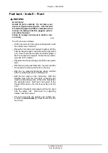
Page 32: ...esult in death or serious injury D0076A NOTE The front tank varies from models TK4020 TK4030 special to models TK4040 TK4050 TK4060 open field There are differences in capacity and shape Proceed as follows 1 Fully raise the engine hood 1 Disconnect the sup porting damper and secure the damper to the restraint bar MOLI11K0031AB 1 2 Detach the plastic side panels 1 on both sides MOLI11K0032AB 2 3 Dr...

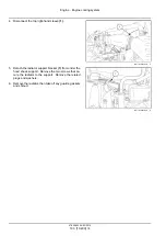
Page 33: ...er hood locking catch and the two spacers alongside the catch from the tank MOLI11K0035AB 5 6 Loosen the clamps on the air cleaner and on the fan manifold retaining the dust ejector pipe 1 Then re move the pipe where applicable On models TK4050 and TK4060 turn the screw 2 by half a turn and extract the heat exchanger 3 Then place the heat exchanger so it does not hinder the up ward movement of its...

Page 34: ...rt Fasten the two retain ing bolts to the radiator Reposition the heat exchanger Refit the dust ejector pipe Refit the two side panel fasteners the catch and the two spacers for closing the hood on the tank Refit the air cleaner turbocharger intake manifold with the related clamps and retaining bolt Refit the two pipes on the intercooler Refit the breather pipe and the two pipes connecting the inj...

Page 35: ...Index Engine 10 Fuel tanks 216 Fuel tank Install Front 9 Fuel tank Install Rear 6 Fuel tank Remove Front 7 Fuel tank Remove Rear 3 47830952 26 03 2015 10 2 10 216 10 ...

Page 36: ...Engine 10 Engine cooling system 400 TK4020F TK4020V TK4030F TK4030V TK4030 TK4040M TK4040 TK4050M TK4050 TK4060 47830952 26 03 2015 10 3 10 400 1 ...

Page 37: ...Contents Engine 10 Engine cooling system 400 SERVICE Radiator Remove 3 Install 5 47830952 26 03 2015 10 3 10 400 2 ...

Page 38: ...rough 7 see Fuel tank Re move 10 216 front Then proceed as described be low 1 Remove the right hand and left hand radiator fan guards 1 2 Drain the expansion tank Loosen the clamp Then remove the expansion tank MOIL14TR00015AB 1 3 Place a container under the cap 1 to collect the engine coolant Then drain the coolant Detach the sleeve 2 from the lower piping on the engine and drain off the remainin...

Page 39: ... Detach the radiator support bracket 1 from under the hood shock support Remove the two screws that se cure the radiator to the support Remove the related plugs and washers 6 Remove the radiator then take off any guards gaskets and shroud MOIL14TR00018AB 4 47830952 26 03 2015 10 3 10 400 4 ...

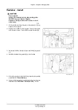
Page 40: ...he support 2 Position the stuffer on the support Secure the stuffer with the two screws Then refit the upper bracket 1 MOIL14TR00018AB 1 3 Reconnect all the various sleeves and fit the plug back on 4 Refit the radiator fan guards 1 on both sides MOIL14TR00015AB 2 5 Fill up the engine coolant with the product and quantity prescribed in Consumables 6 Carry out the assembly operations for the fuel ta...

Page 41: ...This as a preview PDF file from best manuals com Download full PDF manual at best manuals com ...

Reviews: