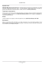
background image

INTRODUCTION

Hydraulic fluid

NEW HOLLAND A

MBRA

H

YDROSYSTEM

46 HV

is specifically designed for high pressure applications and for NEW

HOLLAND CONSTRUCTION hydraulic systems. Your NEW HOLLAND CONSTRUCTION Dealer can provide hy-
draulic fluid to fulfill different climate/temperature conditions. Refer to the

General specification ()

.

Transmission component oil

Extreme pressure oil should be used for enclosed transmission components. Choose an oil that is manufactured for
your climate/temperature conditions such as

NEW HOLLAND A

MBRA

MULTI G 134™

HYDRAULIC TRANSMISSION OIL

.

See

General specification ()

.

Grease

The type of grease to use depends on ambient temperature such as:

NEW HOLLAND A

MBRA

GR 75 MD

.

Environment

Before you service this machine and dispose of oil, fluids, and lubricants, obey environmental regulations. Do not
drain oil or fluids on to the ground or into containers that leak. Check with your local environmental, recycling center
or your Dealer for correct disposal information.

84547255C 15/03/2013

10

Summary of Contents for W270C Tier 4

Page 1: ...Print No 84547255C Wheel Loader Tier 4 W270C W300C SERVICE MANUAL...

Page 2: ...SERVICE MANUAL W270C W300C 84547255C 15 03 2013 EN Find manuals at https best manuals com...

Page 3: ...25 25 100 Powered front axle 25 1 Rear axle system 27 27 100 Powered rear axle 27 1 Brakes and controls 33 33 202 Hydraulic service brakes 33 1 33 110 Parking brake or parking lock 33 2 Hydraulic sys...

Page 4: ...201 Engine starting system 55 4 55 301 Alternator 55 5 55 302 Battery 55 6 55 202 Cold start aid 55 7 55 011 Fuel tank system 55 8 55 988 Selective Catalytic Reduction SCR electrical system 55 9 55 01...

Page 5: ...55 23 55 518 Wiper and washer system 55 24 55 404 External lighting 55 25 55 405 External lighting switches and relays 55 26 55 514 Cab lighting 55 27 55 510 Cab or platform harnesses and connectors 5...

Page 6: ...INTRODUCTION 84547255C 15 03 2013 1 Find manuals at https best manuals com...

Page 7: ...ols Conversion factors 3 Torque 5 Basic instructions 9 Torque Drive shafts center bearing and universal joints 11 Capacities 12 W270C Capacities 13 W300C General specification 14 84547255C 15 03 2013...

Page 8: ...liter 0 033 814 Ounce US fluid Litre 1 056 814 Quart US liquid Litre 0 879 877 Quart Imperial Litre 0 264 172 Gallon US liquid Volume Litre 0 219 969 Gallon Imperial Litre min 0 264 172 Gallon min US...

Page 9: ...ubic yard 0 764 555 Cubic meter Ounce US fluid 29 573 53 Milliliter Quart US liquid 0 946 353 Litre Quart Imperial 1 136 523 Litre Gallon US 3 785 412 Litre Volume Gallons Imperial 4 546 092 Litre Vol...

Page 10: ...542 651 N m 400 480 lb ft 1 0 in 787 944 N m 580 696 lb ft 1 1 8 in 1085 1193 N m 800 880 lb ft 1 1 4 in 1519 1681 N m 1120 1240 lb ft 1 3 8 in 1980 2278 N m 1460 1680 lb ft 1 1 2 in 2631 2983 N m 19...

Page 11: ...61 N m 460 540 lb in M12 90 107 N m 66 79 lb ft M14 144 172 N m 106 127 lb ft M16 217 271 N m 160 200 lb ft M20 434 515 N m 320 380 lb ft M24 675 815 N m 498 601 lb ft M30 1250 1500 N m 922 1106 lb ft...

Page 12: ...N m 125 164 lb ft 38 1 mm 1 50 in 1 7 8 12 285 338 N m 210 249 lb ft Split flange mounting bolts Size Torque 5 16 18 20 27 N m 177 239 lb in 3 8 16 27 34 N m 239 301 lb in 7 16 14 47 61 N m 416 540 l...

Page 13: ...in 3 4 16 61 68 N m 540 602 lb in 10 15 9 mm 0 63 in 1 14 62 76 N m 549 673 lb in 7 8 14 81 88 N m 60 65 lb ft 12 19 mm 0 75 in 1 3 16 12 90 110 N m 66 81 lb ft 1 1 16 12 115 122 N m 85 90 lb ft 14 22...

Page 14: ...a loss of power of the engine and may cause high fuel consumption In very low ambient temperatures use a mixture of fuels No 1 and No 2 as necessary Consult your fuel supplier for appropriate fuel sup...

Page 15: ...ransmission components Choose an oil that is manufactured for your climate temperature conditions such as NEW HOLLAND AMBRA MULTI G 134 HYDRAULIC TRANSMISSION OIL See General specification Grease The...

Page 16: ...Torque Drive shafts center bearing and universal joints Center rear and front drive shaft bolts 136 149 N m 100 110 lb ft Lock nut for yoke on front drive shaft 339 373 N m 250 275 lb ft 84547255C 15...

Page 17: ...V Total system capacity 250 l 66 0 US gal Reservoir capacity 134 l 35 4 US gal Transmission Type of oil NEW HOLLAND AMBRA MULTI G HYDRAULIC TRANSMISSION OIL Service capacity with filter change 45 4 l...

Page 18: ...STEM 46 HV Total system capacity 250 l 66 US gal Reservoir capacity 134 l 35 4 US gal Transmission Type of oil NEW HOLLAND AMBRA MULTI G 134 HYDRAULIC TRANSMISSION OIL Service capacity with filter cha...

Page 19: ...INTRODUCTION General specification Hydraulic oil temperature chart LELI12WL30001EA 1 Transmission oil temperature chart LEIL12WHL0011BA 2 84547255C 15 03 2013 14...

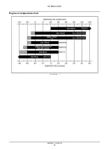
Page 20: ...INTRODUCTION Engine oil temperature chart LEIL12WHL0018BA 3 84547255C 15 03 2013 15...

Page 21: ...INTRODUCTION 84547255C 15 03 2013 16...

Page 22: ...SERVICE MANUAL Engine W270C W300C 84547255C 15 03 2013 10...

Page 23: ...10 1 W270C W300C 10 202 Air cleaners and lines 10 2 W270C W300C 10 500 Selective Catalytic Reduction SCR exhaust treatment 10 3 W270C W300C 10 400 Engine cooling system 10 4 W270C W300C 10 310 Afterc...

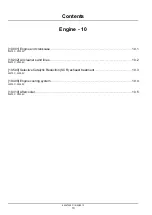
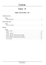
Page 24: ...Engine 10 Engine and crankcase 001 W270C W300C 84547255C 15 03 2013 10 1 10 001 1...

Page 25: ...ine Overview Stall tests 4 SERVICE Engine Remove Engine 6 Install 16 Prepare Stall tests 25 Prepare Stall tests Heat the oil torque converter 26 Prepare Stall tests Heat the oil hydraulic system 27 Se...

Page 26: ...PM B Maximum no load 2162 2212 RPM C Converter stall 1st gear 1970 RPM 2nd 4th gear 2075 RPM D Hydraulic stall 1885 2195 RPM E Converter hydraulic stall 1665 RPM NOTE Hydraulic stall and converter hyd...

Page 27: ...he normal driving screen 2 From the driving screen push the down arrow as shown LEPH12WL30050AA 1 3 Info 1 is the first information screen using the down arrow from the driving screen It displays engi...

Page 28: ...ature Urea temperature and Urea level LELI12WL30054AA 5 7 Press the down button again and the Trip 1 screen will display The LCD provides two trip computers These will display since last reset the tot...

Page 29: ...ease any hydraulic pressure in the lift circuit 4 Move the loader control handle in and out of the tilt position several times this will relieve any pressure in the pilot accumulator 5 Release the pre...

Page 30: ...AB 4 13 Remove the SCR line support bracket 1 LELI12WL30009AB 5 14 Disconnect the deaeration tank overflow hose 2 Remove the P clamps 1 that secure the overflow hose to the wall and brackets Position...

Page 31: ...the bulkheads 2 LELI12WL30013AB 9 18 Remove the oil dipstick P clamp 3 Pull the oil dip stick tube 1 through the wall Label and disconnect the hood lift strut electrical connector 2 LELI12WL30014AB 10...

Page 32: ...er restriction sensor electri cal connector 3 LELI12WL30016AB 12 21 Remove the wire harness P clamp 1 Loosen the hose clamp on the air box snorkel 2 Disconnect the air box snorkel 3 LELI12WL30017AB 13...

Page 33: ...lifting equipment to the engine wall Remove the engine wall s hold down bolts Lift and remove the engine wall LELI12WL30021AA 17 26 Remove the turbo exhaust tube 1 LELI12WL30022AB 18 27 Disconnect th...

Page 34: ...2 LELI12WL30026AB 22 31 Disconnect the following from the crank case venti lation fuel filter bracket assembly Fuel pump electrical connector Water sensor electrical connector Ground wire Wire harnes...

Page 35: ...28AB 24 34 Disconnect the fuel return line 1 Disconnect the battery positive wire 2 on the air grid heater LELI12WL30029AB 25 35 Disconnect the engine ground wires 1 Remove the wire harness P clamp 2...

Page 36: ...wire 3 Label and discon nect the bulk electrical connector 5 Remove the A C compressor 2 Position the A C com pressor 2 away from the engine LELI12WL30032AB 28 38 Remove the wire harness P clamps 1 LE...

Page 37: ...draulic oil return tube away from the con verter housing cover plate LELI12WL30036AB 32 42 Remove the converter housing cover plate 1 LELI12WL30037AB 33 43 Remove the flex plate bolts 1 LELI12WL30038A...

Page 38: ...rankcase 45 Remove the front engine mounts 1 and engine mount plate 2 LELI12WL30040AB 36 46 Remove the bell housing bolts 1 LELI12WL30041AD 37 47 Remove the engine LELI12WL30035AA 38 84547255C 15 03 2...

Page 39: ...a torque value Tighten the engine bracket upper bolts 2 to a torque of 171 231 N m 126 170 lb ft Tighten the engine bracket lower bolts 3 to a torque of 69 80 N m 51 59 lb ft Tighten the engine mount...

Page 40: ...ly DOW 732 RTV SILICONE CLEAR to the con verter housing cover plate 1 Install the converter housing cover plate 1 LELI12WL30037AB 6 7 Connect the inlet and outlet heater core heater hoses 1 LELI12WL30...

Page 41: ...bolts 2 washers 3 and nuts 4 LELI12WL30024AB 9 10 Connect the SCR coolant solenoid heater hose 1 LELI12WL30023AB 10 11 Install the turbo exhaust tube 1 LELI12WL30022AB 11 12 Remove lifting equipment...

Page 42: ...13 14 Install the lower radiator tube 1 LELI12WL30020AB 14 15 Install the air box LELI12WL30019AA 15 16 Install the wire harness P clamp 1 Connect the air box snorkel 3 Tighten the hose clamp on the a...

Page 43: ...tube 2 Connect the humidity sensor electrical connector 1 Connect the air filter restriction sensor electrical connector 3 LELI12WL30016AB 18 19 Install the upper radiator tube 2 Install the before ai...

Page 44: ...all the A C compressor 2 Connect the A C compressor electrical connector 1 Connect the A C pressure switch electrical connector 4 Connect the alternator power wire 3 Connect the bulk electrical connec...

Page 45: ...racket as sembly 28 Connect the following on the crank case ventilation fuel filter bracket assembly Fuel pump electrical connector Water sensor electrical connector Ground wire Wire harness P clamp C...

Page 46: ...ough the engine wall Install the dipstick tube P clamp 3 LELI12WL30014AB 29 31 Install the bulkheads 2 Install the after air cooler tube 1 LELI12WL30013AB 30 32 Install the hydraulic lines 1 LELI12WL3...

Page 47: ...I12WL30009AB 34 36 Lower the exhaust stack hood 1 in front of the en gine wall and onto the left bracket right bracket and hydraulic oil tank Install the exhaust stack hood mounting bolts LELI12WL3000...

Page 48: ...works against the torque converter the hydraulic system or both the torque converter and the hy draulic system The results of these tests will show if the cause of poor performance is one or more of t...

Page 49: ...automatic switch in the manual mode po sition Push down and hold the brake pedal for the remainder of this procedure 6 Release the parking brake 7 Move the transmission control lever to forward and t...

Page 50: ...ure with the instrument cluster A Press the up or down arrow key B Stop at the info screen with the temperatures that need to be monitored are on 4 Hold the bucket control lever in the ROLLBACK po sit...

Page 51: ...ve at the above service screen 3 Use down arrow to scroll through the menu s 4 High light Power Mode and press the enter key LEPH12WL30057AA 1 5 Power Mode Menu A Max Maximum power possible B Standard...

Page 52: ...Lower the bucket to the ground place the transmis sion in neutral and apply the parking brake 12 Stop the engine Understanding the results of test No 1 1 If the engine speed was as specified the engi...

Page 53: ...to full throttle 4 Hold the bucket control lever in the ROLLBACK po sition and raise the lift arms The stall speed must be read while the lift arms are in motion 5 Check the engine speed 6 Release th...

Page 54: ...ll tests 4 Engine Prepare Stall tests 25 Engine Prepare Stall tests Heat the oil hydraulic system 27 Engine Prepare Stall tests Heat the oil torque converter 26 Engine Remove Engine 6 Engine Service i...

Page 55: ...84547255C 15 03 2013 10 1 10 001 32...

Page 56: ...Engine 10 Air cleaners and lines 202 W270C W300C 84547255C 15 03 2013 10 2 10 202 1...

Page 57: ...Contents Engine 10 Air cleaners and lines 202 SERVICE Air cleaner Assemble Primary secondary filter element 3 Disassemble Primary Secondary filter element 5 84547255C 15 03 2013 10 2 10 202 2...

Page 58: ...ll new primary filter element by sliding it down into housing NOTE Make sure primary and secondary filter elements form an effective seal LELI12WL30136AB 2 3 Install housing cover LELI12WL30135AA 3 4...

Page 59: ...Engine Air cleaners and lines 5 Turn master electric power switch ON Clear any fault codes Start machine and confirm problem has been corrected LELI12WL30110AB 5 84547255C 15 03 2013 10 2 10 202 4...

Page 60: ...g controls lo cated behind access cover 1 Air filter housing el ement 2 is located in main engine compartment on right hand side of engine LELI12WL30133BB 1 2 Turn master electric switch OFF LELI12WL3...

Page 61: ...This as a preview PDF file from best manuals com Download full PDF manual at best manuals com...

Reviews:

Related manuals for W270C Tier 4