5
1
1
.
.
A
A
p
p
p
p
e
e
a
a
r
r
a
a
n
n
c
c
e
e
2
2
.
.
P
P
a
a
r
r
t
t
n
n
a
a
m
m
e
e
s
s
a
a
n
n
d
d
a
a
c
c
c
c
e
e
s
s
s
s
o
o
r
r
i
i
e
e
s
s
N
N
o
o
.
.
P
P
a
a
r
r
t
t
N
N
a
a
m
m
e
e
D
D
e
e
s
s
c
c
r
r
i
i
p
p
t
t
i
i
o
o
n
n
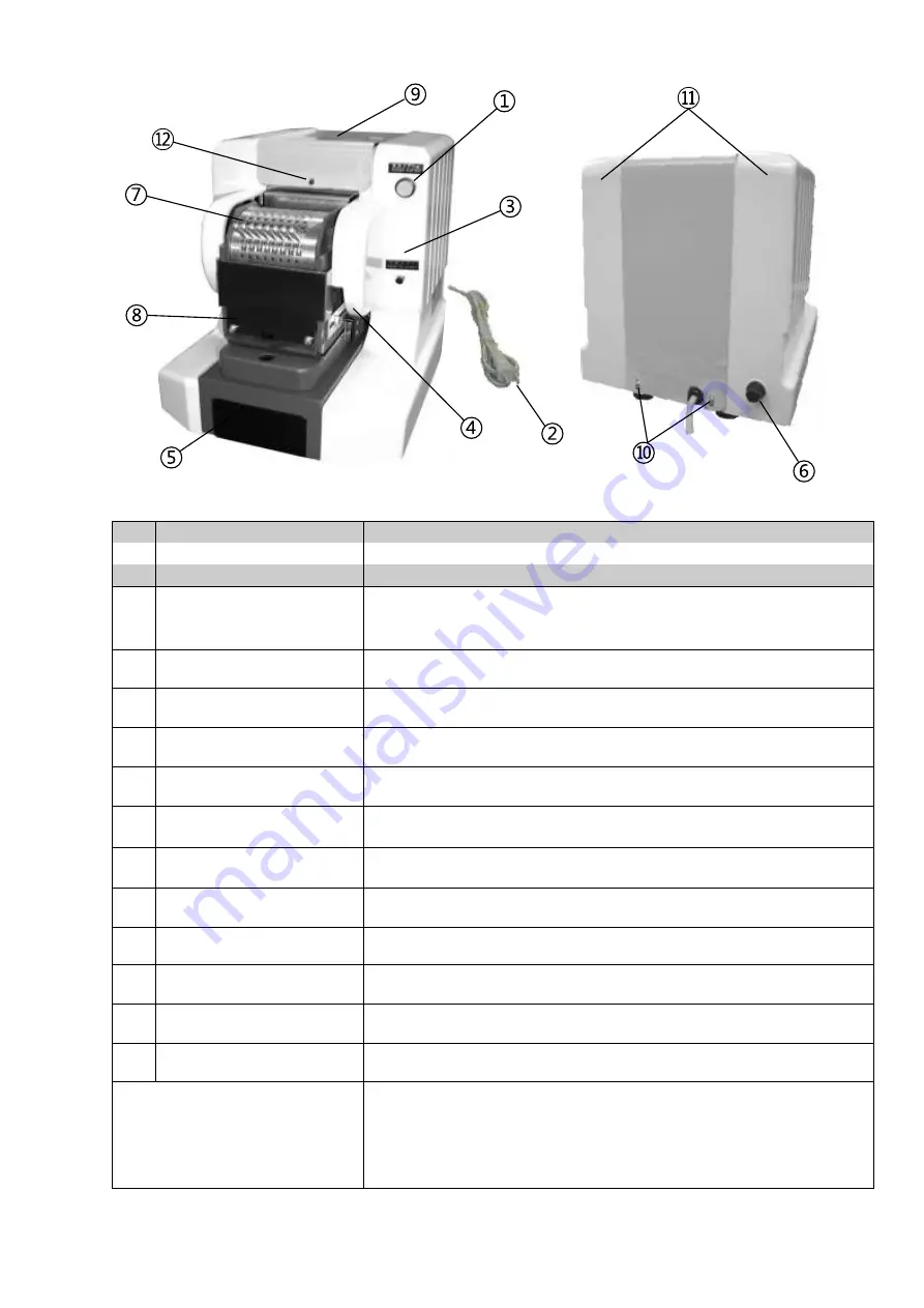
①
Main Switch
Push button switch that turns on the power supply.
(The green lamp lights up.)
②
Electric cord with plug
Plug unit into a suitable wall outlet.
③
Operating switch
Push button for manual operation if the depth switch cannot be used.
④
Micro switch
Switch for detecting when paper is inserted and the machine can punch.
⑤
Waste Drawer
Drawer for paper chip storage. Must check and empty it frequently (it is
advisable to check daily).
⑥
Fuse box
Turns off the power when an excessive electric load is applied to the product.
⑦
Die block
This is the perforation die block.
⑧
Feed opening
Paper insertion area.
⑨
Top cover
A green protective cover is attached. (Please peel off before using).
⑩
Truss head screw
Screws for attaching the top cover.
⑪
Side covers
Left and Right Side Covers
⑫
Pin
This pin fits into the hole in front of the cover when installing the top cover.
Accessory bag list
1 each Operating manual
1 each
spare fuse (5 amp)
1 each 6mm L shape hexagonal wrench
1 each dust cover
Summary of Contents for 10 Series
Page 17: ...17 ...


