- 30 -
www.NewLeader.com
(800) 363-1771
307369-AA-G
L3030G4 CNH
Header
Insert Installation
FEEDGATE ADJUSTMENT
WARNING
Stay out of the spreader. If it’s necessary to enter the spreader, return to the shop, empty
body, turn off all power, set vehicle brakes, lock engine starting switch and remove keys
before entering. Tag all controls to prohibit operation. Tags should be placed, and later
removed, only by person working in the body.
Adjust the insert’s front feedgate prior to installation.
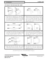
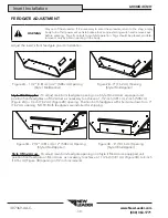
Figure 2A - 1 1/2” (3.81 cm) or 2” (5.08 cm) Opening
(Style I MultApplier)
Figure 2B - 3” (7.62 cm) Opening
(Style I MultApplier)
Style I MultApplier
- To adjust main bin’s feedgate opening on a Style I M
ULT
A
PPLIER
-equipped unit:
position front feedgates on M
ULT
A
PPLIER
as necessary to achieve a 1-1/2 inch (3.81 cm), 2 inch (5.08 cm)
(Figure 2A) or 3 inch (7.62 cm) (Figure 2B) opening. Position both feedgates with short side down for a 3”
(7.62 cm) opening. NOTE: Both feedgates are installed for shipping.
Figure 3A - 2 1/2” (3.81 cm) or 2” (5.08 cm) Opening
(Style II MultApplier)
Figure 3B - 4” (10.16 cm) Opening
(Style II MultApplier)
Style II M
ULT
A
PPLIER
- To adjust main bin’s feedgate opening on a Style II M
ULT
A
PPLIER
-equipped unit:
position front feedgate on M
ULT
A
PPLIER
as necessary to achieve a 1 1/2 inch (3.81 cm) (Figure 3A) to 4 inch
(10.16 cm) (Figure 3B) opening in 1/2 inch increments.

