- 33 -
L3030G4 CNH
www.NewLeader.com
(800) 363-1771
307369-AA-G
Header
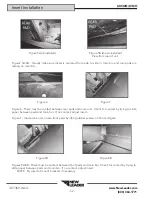
Figure 9
Figure 10
Figure 11
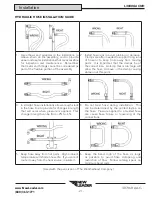
Figure 9 - Once both front pads make contact, insert hardware in front mount brackets’ lower holes.
Shim between main bin and insert brackets if distance is larger than 1/8” (.32cm). Tighten hardware per
torque recommendations in this manual.
Figure 10 - Make sure front feedgate is level. Lower endgate sealers so
fl
ush with chain shields and
tighten hardware.
NOTICE!
Leakage of material may occur if the sealer belts are not set properly on the front of the
insert. Highway Equipment Company is not liable for lost material due to improperly
installed sealer belts.
Figure 11 - Make sure there is a complete seal covering the gap between the insert and the main bin’s
side sheets. Tighten all hardware on rubber sealers at front of insert.
Make sure rear pads are still in place against main bin. Install hardware in lower holes of rear mount
brackets. Shim between main bin and insert brackets if distance is larger than 1/8” (.32cm). Tighten
hardware per torque recommendations in this manual.
Make sure insert’s side sheets are not resting on top of main bin’s side sheets.
Install hardware in all four mount brackets’ upper holes. Tighten hardware per torque recommendations.
Remove hoist.
Inspect unit for foreign debris in conveyor area.
Insert Installation

