background image

- 127 -

L5034G4

www.NewLeader.com
(800) 363-1771

305438-J

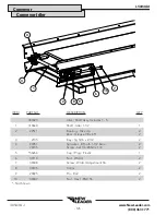
Encoder

Conveyor

2

1

1

5

4

4

2

3

5

ENCODER 

REMOVED

2

3

4

5

1

1

ITEM

PART NO�

DESCRIPTION

QTY

1

303994

Encoder – 180 with Hardware

1

2

310601

Coupler - Rate Sensor SS

1

3

310603

Screw - Set 1/4-20NC x 5/16 SS

1

4

81949

Bracket - Sensor, Idler Mount

1

5

2696

Collar - Set 1”

1

Summary of Contents for L5034 G4

Page 1: ...Manual UNIT SERIAL NUMBER ___________________________ MANUAL NUMBER 305438 J EFFECTIVE 08 2022 1330 76TH AVE SW CEDAR RAPIDS IA 52404 7052 PHONE 800 363 1771 FAX 319 286 3350 www newleader com Copyrig...

Page 2: ...ation 32 Operations Maintenance 35 General Description 35 Dimensions Capacities 36 Initial Start up 37 Field Testing 38 General Operating Procedures 39 Lubrication Maintenance 40 Preventative Maintena...

Page 3: ...Alarm Settings 64 Reconfigure System 64 Switch Assignment 65 Component Calibration 66 Spinner Disc Calibration 66 Conveyor Calibration 67 Operations Features 70 Hydraulics 74 Bin Flush 75 Body Module...

Page 4: ...e 114 PWM Spinner Speed Controller 115 Hydraulic Reservoir 116 Hydraulic Reservoir w Cooler 118 Conveyor 122 1 Bar Chain Conveyor 122 2 3 Bar Chain Conveyors 123 Chain Shields 124 Conveyor Drive 125 C...

Page 5: ...se of these features Hyperlinks Hyperlinks provide direct access to a specific destination when clicked The entire Table of Contents of this manual is hyperlinked to provide quick access to all sectio...

Page 6: ...Insert Current New Leader Warranty Warranty...

Page 7: ...SAFETY...

Page 8: ...rized dealer or our Product Sales and Support Department at 1 888 363 8006 It has been our experience that by following these installation instructions and by observing the operation of the spreader y...

Page 9: ...loyer of the user and or assistants must provide adequate and necessary training to ensure proper operation and compliance with all safety procedures pertaining to this equipment If Operator s Manual...

Page 10: ...specified parts Tighten all bolts nuts and screws to specified torques Refer to Standard Torques in Maintenance section of this manual Figure 1 3 HANDLE FLAMMABLE MATERIALS SAFELY Figure 1 4 Handle f...

Page 11: ...engine inside a building unless adequate ventilation is provided to safely and properly remove exhaust fumes Failure to comply with this requirement could result in death or serious injury Figure 1 6...

Page 12: ...adjusting or servicing Keep hands feet hair and clothing away from moving parts Figure 1 9 Figure 1 10 Keep away from spinners while they are turning Rocks scrap metal and other material can be throw...

Page 13: ...E MACHINE SAFELY Always walk around and visually inspect machine before using Check the immediate vicinity of machine for people and obstructions Ensure adequate visibility Avoid distractions such as...

Page 14: ...hts turn indicators parking brake horn and rear view mirrors Repair or replace any component that is not in proper working order Never drive machine at a speed that causes it to bounce or cause loss o...

Page 15: ...nents while they are moving Never wear loose clothing or jewelry when working near machine tools or moving parts Remove rings and other jewelry to prevent electrical shorts and other personal injury w...

Page 16: ...ediately Always have a multipurpose dry chemical fire extinguisher filled and available Know how to use it Maintenance General Safety Rules USE PROPER LIFTING EQUIPMENT Figure 3 5 Use only lifting dev...

Page 17: ...nders Do not heat by welding soldering or using a torch near pressurized fluid lines or other flammable materials Pressure lines can suddenly burst when heat goes beyond the immediate flame area Figur...

Page 18: ...rim can cause an explosion and serious injury Tire service procedures must be performed by trained and qualified personnel Figure 3 12 CLEAN MACHINE OF HAZARDOUS CHEMICALS During application of hazard...

Page 19: ...ifting device to free machine from a chassis storage stands or frozen ground or to lift the chassis in any way Shock loading is prohibited and sudden accelerations must be avoided Lifting in such a ma...

Page 20: ...to these Remove the Liner A small bend at the corner or edge will cause the liner to separate from the decal Pull the liner away in a continuous motion at a 180 degree angle If the liner is scored ben...

Page 21: ...use If manual is missing contact dealer for replacement 2 DANGER MOVING PART HAZARD To prevent death or serious injury Stay out of box while conveyor is moving Disconnect and lock out power source bef...

Page 22: ...ssure to the system Wear protective gloves and safety glasses or goggles when searching for leaks Use wood or cardboard instead of hands Do not use hydraulic lines for hand holds or steps Components m...

Page 23: ...INNER HAZARD To prevent death or serious injury Wear eye protection Stop machine before servicing or adjusting Keep bystanders at least 60 feet away 8 WARNING FALLING HAZARD To prevent death or seriou...

Page 24: ...Pattern manual for adjustment instructions A spread pattern test kit is available from your New Leader dealer Wind humidity rain and other adverse weather conditions can affect spread pattern resulti...

Page 25: ...e chain links loose and free running can result in severe damage to the conveyor chain drag shaft gearcase and body structure and is cause for voiding the warranty 3 NOTICE HYDRAULIC RESERVOIR To avoi...

Page 26: ...INSTALLATION...

Page 27: ...tion of chassis hydraulic hose and electrical wiring to spreader Installation of optional parts Filling of hydraulic reservoir and lubrication Checking for leaks and proper functioning Truck Requireme...

Page 28: ...taching chains in a near vertical orientation as shown in Figure 1 Operators of lifting devices must be qualified and knowledgeable in their use and application Position the chassis with adequate room...

Page 29: ...les where marked and install mounting assembly using 1 2 hardware supplied Weld mounting plate to bottom of cross tube on three sides and remove 3 8 10mm shim Figure 2 Tighten spring assembly until sp...

Page 30: ...ounting angles and spreader cross tubes are sound full fillet welds Center mounting angles on tubes as shown in Figure 3 so full fillet welds can be made on three sides An edge bead weld is not a sati...

Page 31: ...gle Installation Figure 5 Fender Installation Fenders may not be as shown Attach fender angles and panels on spreader body stakes as shown in Figure 4 Do not tighten hardware at this time Attach fende...

Page 32: ...or contact hot or moving parts Hydraulic Pump Installation HECO pumps are direct mount See Pump Hydraulics in the spreader parts manual for assembly instructions Figure 7 Hydraulic Pump Installation...

Page 33: ...ow the hose to move in the clamp causing abrasion at this point 3 In straight hose installations allow enough slack in the hose line to provide for changes in length that will occur when pressure is a...

Page 34: ...l reservoir with hydraulic oil as specified in the Lubrication and Maintenance section in the operator s manual Be sure oil is clean free from dirt water and other contaminants Lubricate all points ne...

Page 35: ...33 This page is intentionally left blank L5034G4 www NewLeader com 800 363 1771 305438 J Notes...

Page 36: ...34 This page is intentionally left blank www NewLeader com 800 363 1771 305438 J L5034G4 Notes...

Page 37: ...OPERATIONS MAINTENANCE...

Page 38: ...of the hopper bottom to deliver material to the spinners through a hydraulically adjustable metering gate at the rear of the hopper body A feedgate sight gauge allows monitoring of the feedgate openi...

Page 39: ...mm CA 14 208 5283mm 156 3962mm 159 4039mm 114 2896mm CA 16 232 5893mm 180 4572mm 183 4648mm 138 3505mm CA 120 3048mm CT 18 256 6502mm 204 5182mm 207 5258mm 153 3886mm CA 144 3658mm CT 21 292 7417mm 24...

Page 40: ...Run conveyor at 0RPM and spinner at 0RPM Make sure both conveyor and spinner do not move 10 Calibrate spreader as defined in the manual for the controller that is supplied with your machine 11 Comple...

Page 41: ...body or on any part of spreader as there is danger of falling off the vehicle or into moving parts Use great care in performing this test Failure to comply with this requirement could result in death...

Page 42: ...ad pattern desired Calibrate and spread pattern test for any new material 5 Fill applicable bins with material to be spread 6 Engage hydraulics 7 Begin spreading Drive only at speeds which permit secu...

Page 43: ...with hydraulic fluid at high pressure seek immediate medical attention as fluid injected into the skin could cause gangrene if left untreated Relieve pressure before disconnecting hydraulic lines or...

Page 44: ...should be hydrostatically tested at twice the recommended working pressure of the hose Test pressure should be held for not more than one minute and not less than 30 seconds When test pressure is reac...

Page 45: ...excessive load on the system causing excessive chain and sprocket wear and can cause extremely high starting pressures Under tensioning allows conveyor chain to wrap around drive sprockets and not exi...

Page 46: ...hose from outside of spreader Do not aim high pressure sprayer directly at sensor it could damage the components Lubrication of Bearings Grease in a bearing acts to prevent excessive wear of parts pr...

Page 47: ...emperatures listed below Single Pinion 1 Pint 50 L Dual Pinion 1 5 Pints 70 L Ambient Temperature Oil Type 40 F 4 44 C SAE 80 E P SAE 90 E P SAE 100 E P 100 F 37 77 C Ambient Temperature Oil Type Figu...

Page 48: ...raulic System Reservoir 1 Check Daily Change Annually Filter 1 Check daily Change when indicated Red Conveyor Grease Zerks Dragshaft Bearings 2 Grease Gun Weekly Grease Zerks Idler Shaft Bearings 2 Gr...

Page 49: ...3 Chain Poultry Litter 16 54 256 865 X O O Waste Sludge 40 65 641 1041 X O O Paper Pulp approx 42 673 X O O Compost Cattle Manure 36 65 577 1041 X O O Gin Trash 35 50 561 801 NR O X Fly Ash 38 45 609...

Page 50: ...47 L5034G4 www NewLeader com 800 363 1771 305438 J Troubleshooting Hydraulic Schematic...

Page 51: ...er motors Free up If not possible replace as required 7 Jammed or frozen conveyor Free up conveyor 8 Defective radar Check speed on console Repair or replace radar as required 9 Control processor s po...

Page 52: ...cent PTO or use larger pump Special 15 Defective spinner control valve Replace valve metering spool spring If no improvement replace spinner control valve 16 Cab control is for conveyor only spinners...

Page 53: ...DEGREES APART USE GRADE 2 TORQUES FOR STAINLESS STEEL FASTENERS AND CARRIAGE BOLTS TORQUE FOOT POUNDS CAP SCREW SIZE GRADE 2 GRADE 5 GRADE 8 DRY LUBE DRY LUBE DRY LUBE 1 4 5 4 8 6 12 9 5 16 11 8 17 13...

Page 54: ...CONTROLLER...

Page 55: ...y switching back and forth between different VT s Terminologies ISOBUS An electronic communications network used on agricultural and forestry equipment that adheres to the ISO 11783 standards VT Virtu...

Page 56: ...gram ISOBUS CAN Proprietary CAN High Current Power Signal Cab to Enclosure VT Battery To ECU Enclosure To ECU Enclosure Terminating Plug Radar Existing CAN BUS Customer supplied Customer supplied Cust...

Page 57: ...ter Restriction Panel Mount Connections Hydraulic Cooler Fan 30 AMP Ground 60 AMP Ground Conveyor Conveyor Conveyor Control Conveyor Control Speed Conveyor Speed Bin Low Sensor Bin Low Sensor Conveyor...

Page 58: ...supports AUX N functionality Task Control Multi product up to 4 bins Function VT will load New Leader UI and assign functions to in cab switches TC BAS Ability to track totals TC GEO Ability to log as...

Page 59: ...f VT will bring up the New Leader Home Screen also called the Run Screen as shown in Figure 1 A B C D E F G H J K L M N P Q R S T Figure 1 Home Screen A Spreader Operations K Target Rate 1 B Density L...

Page 60: ...nfiguration settings and calibration numbers Press the keypad button to access the on screen numeric entry screen Keypads may look different depending on VT being used Figure 3 Numeric Keypad Navigati...

Page 61: ...on may need to be built See Manufacturer s Operations Manual for detailed instructions on these processes Initial Configuration Factory Setup Only seen on first boot or if system is reset reconfigured...

Page 62: ...nabled disabled and Pressure Transducer calibration Enter Capacity for Main Bin using keypad Enable or disable bin level sensor as required Press to edit pressure transducer settings If standard trans...

Page 63: ...L5034G4 www NewLeader com 800 363 1771 305438 J Repeat step 3 for MultiBin Micro 1 as necessary Press to continue Repeat step 3 for MultiBin Micro 2 as necessary Press to continue Controller Operatio...

Page 64: ...of the spinner disc b For self propelled units enter the distance from the center of the rear axle to the center of the spinner disc a NOTE For units and trailers with tandem axles use the center of t...

Page 65: ...settings Press to to enable disable bins Enable Disable Bins Each Installed Bin as set up in Step 4 will appear Press each Enable button to enable or disable each bin as appropriate for the current jo...

Page 66: ...er to hit target rate sooner IMPORTANT Setting Zero Flow Offset too high will cause spinners to overshoot Low Spinner Speeds and could cause delay in reaching set speed Adjust as needed in small incre...

Page 67: ...owing servo valve response Allowable Error Determines the percent of error that is allowed prior to product control system making any flow rate changes 2 3 is normal dead band setting range PWM PWM Fr...

Page 68: ...restore all settings to factory default and all calibration numbers will be lost It should only be pressed if instructed to do so by service technician or New Leader product support Press to reset re...

Page 69: ...ss to automatically map the switches to the correct function Controller Operations Reconfigure allows the user to adjust any of the system settings made during first time start up Machine Configuratio...

Page 70: ...ower up Display Monitor and activate VT The Run screen will appear Press to continue Spinner Disc Calibration Press to calibrate spinner discs Use keypad to edit numeric setting as necessary Standard...

Page 71: ...the bin to be tested To perform in field calibration press for the bin to be tested Do not work near rotating spinners Severe injury can result from contact with moving parts Failure to comply with th...

Page 72: ...l stop Press to continue Weigh material dispensed and enter actual weight of material dispensed Press to continue It is recommended a minimum of three 3 tests be done PER PRODUCT to ensure accuracy On...

Page 73: ...n field screen displays system perceived total of dispensed product To enter actual dispensed amount press Using keypad enter actual weight of product dispensed Press to continue New cubic feet per re...

Page 74: ...y to display Refer to display manual on how to create a job using Task Control When finished activate VT 2 Verify Product Density Material Density will vary from product to product It is imperative th...

Page 75: ...nt products may require different spread widths or spinner speeds Always verify the material profile is configured correctly before applying product Edit current profile or create a new one if necessa...

Page 76: ...set feedgate opening to correct reading 6 Verify CFR number is correct Different products may require different calibration numbers Verify the CFR number is correct before applying product Press then...

Page 77: ...NewLeader com 800 363 1771 305438 J To view unlocked features press Current unlocked features will display Press Unlock to display module serial number and registration number Press to return Control...

Page 78: ...iew hydraulic monitoring Hydraulics System pressure Temperature and status of Fluid Level and Filter Restrictions will show system wide Conveyor Pressure will display for Bin 1 and cumulatively for Bi...

Page 79: ...he Tools main screen will appear Press to continue Do not work near rotating spinners Severe injury can result from contact with moving parts Failure to comply with this requirement could result in de...

Page 80: ...m 60 RPM Bins 3 4 Maximum 85 RPM Press to continue 4 Perform bin flush To flush bins press Conveyors will run until is pressed When process completes press to continue Do not work near rotating spinne...

Page 81: ...ay Monitor and activate VT The Run screen will appear Press to continue The Tools main screen will appear Press to continue Bin Cover Control If equipped press A to open and close tarp If MultiBin ins...

Page 82: ...alarm frequency and set auto lube settings 1 Power up Display Monitor and activate VT The Run screen will appear Press to continue The Tools main screen will appear Press to continue 2 Set duration Us...

Page 83: ...length and sprocket diameter Press to return to Chain Oiler screen Press to return to Tools Screen 4 Set service reminder Press Service Reminder to set chain oiler reminder Enable Reminder and use ke...

Page 84: ...heck the ISOBUS connections WSM Spreader Module CAN Power Voltage Low The CAN power voltage is below 8 0 volts Check CAN bus power supply WSM Spreader Module High Power Voltage Low The high power volt...

Page 85: ...c control to a field ready condition The spinners will now restart At the end of the Static Conveyor Calibration routine and Conveyor flush routine Boundary Spinner Not Responding Boundary Spinner Not...

Page 86: ...F Basic Independent Spinners Not Responding Spinner Not Responding Spinner Name enabled CLF Mode Basic Independent must be selected At least one product bin must be commanded on Perceived spinner spee...

Page 87: ...Operating Range Hydraulic temperature is below 65 F 18 C Hydraulic fluid too cold to operate machine Hydraulic Fluid Temperature Exceeds Maximum Hydraulic Fluid Temperature Exceeds Maximum Operating R...

Page 88: ...tion in Operations section of this manual for details Refer to Dimensions Capacities in Operations section of this manual for capacities on all applicable bin configurations Pressure Transducer Settin...

Page 89: ...sponse 2 8 8 8 8 Response Threshold 4 0 4 0 4 0 4 0 Allowable Error 1 1 1 1 Sensor Settings Encoder pulses 180 or 360 verify by looking on encoder Spinner pulses 4 Alarms Alarm Settings Alarm Variable...

Page 90: ...86 www NewLeader com 800 363 1771 305438 J L5034G4 This page is intentionally left blank Notes Notes...

Page 91: ...SPREAD PATTERN...

Page 92: ...from the catching device Do not remove material from spinner discs 7 Measure the depth of material on the end of the conveyor to verify the constant number feedgate height information entered into the...

Page 93: ...n kit is available to aid in measuring product quality Contact your local dealer for details Use great caution while working around the spreader Contact with spinners and other moving parts is very da...

Page 94: ...der to be tested must be in good mechanical condition and properly adjusted Refer to operator s manual for details All damaged and worn parts must be replaced Spinner discs and fins must be free of an...

Page 95: ...d Speed mph Rate lbs Feedgate in Spinner Frame Setting Spinner RPM Lime 90 11 1000 5000 6 5 600 2000 8000 12 5 600 Urea 46 18 110 2 5 4 800 225 2 5 3 5 800 450 2 5 2 5 800 Corn Blend 53 18 125 2 5 3 5...

Page 96: ...raight 41 5 10am Figure 1 Select an area for testing measuring at least 120 feet x 200 feet 37 m x 61 m and with a slope of less than two degrees All testing should be done when the wind velocity is l...

Page 97: ...00 100 75 75 20 30 40 50 60 70 80 90 100 110 20 30 40 50 60 70 80 90 100 110 0 120 120 60 60 Figure 2 Four Wheeled Vehicles Three Wheeled Vehicles For three wheeled application vehicles straddling the...

Page 98: ...data sheet under the corresponding tray position and graph the spread pattern profile See Figure 4 313964 A Temperature F lbs acre Spinner Speed RPM Controller Vehicle Speed MPH Controller Swath Widt...

Page 99: ...e spinner rearward away from conveyor Light Outside Vehicle s Tire Tracks RATE ACRE 1 Check spinner fins for material buildup rust or paint 2 Increase spinner RPM 3 Move spinner fins to 2 3 2 3 positi...

Page 100: ...age amount at the center of the pattern In the example shown in Figure 8 these points are located 45 to the left of center and 45 to the right of center The distance between these two points 90 repres...

Page 101: ...enter of the trays down the AB line 5 Drive through the row of trays and switch back once again driving past the trays on the opposite side at an equal distance from the AB line as the first pass R20...

Page 102: ...PARTS...

Page 103: ...mpany No responsibility is assumed for delay or damage to merchandise while in transit Our responsibility ceases upon delivery of shipment to the transportation company from whom a receipt is received...

Page 104: ...IPTION QTY 1 20131 Cap Screw 1 2 13NC x 2 AR 2 20695 Washer Flat 1 2 12 3 20680 Nut Lock 1 2 13NC AR 4 41762 Nut Lock 5 8 11NC 4 5 20195 Cap Screw 5 8 11NC x 6 1 2 4 6 20697 Washer Flat 5 8 4 7 31856...

Page 105: ...PTION QTY 1 80831 Window Sight 8 x 10 1 2 80832 X1 Bar Retainer Side 8 x 10 304 2 3 80833 X1 Bar Retainer Top Bottom 8 x 10 2 4 42033 Screw Truss Head 1 4 x 1 SS 14 5 42034 Nut Lock 1 4 SS 14 Type II...

Page 106: ...100 www NewLeader com 800 363 1771 305438 J L5034G4 Feedgate Body 2 3 4 5 7 1 13 14 15 8 9 11 10 8 9 11 12...

Page 107: ...w chain shields 1 305473 303298 Feedgate Wldmt 34 w o chain shields 1 5 303379 303325 Bracket Indicator 1 6 55395 55395 Decal Indicator 1 7 303324 303323 Indicator Feedgate 1 8 20068 36399 Cap Screw...

Page 108: ...6 Unit 1 303376 83083 X2 303378 Fender LH 18 Unit 1 304477 306258 304479 Fender LH 21 Unit 1 3 83021 96969 96969 Angle Mounting AR 4 83017 96965 96965 Formed Angle RH 1 5 83018 96966 96966 Formed Angl...

Page 109: ...dy ITEM PART NO DESCRIPTION QTY 46474 Hardware Kit Includes 3 6 1 21770 Mudflap Plain 2 304245 Mudflap Midguard 2 2 36844 Rod Mudflap 2 3 20067 Cap Screw 3 8 16 x 1 8 4 20693 Washer Flat 3 8 8 5 20712...

Page 110: ...104 www NewLeader com 800 363 1771 305438 J L5034G4 Pump Hydraulics Body Hydraulics 14 13 15 17 16 11 12 18 10 9 17 16 5 4 7 8 2 3 1 6 2 3 1 2 3 4 5 6 7 8 9 11 12 13 14 15 16 17 18 10 1 2 3 1 16 17...

Page 111: ...ting 32 32 12151 3 E90S L 1 6 29840 Fitting Elbow 90 1 7 304427 Fitting 20 20 430260 1 8 29789 Fitting 12 12 070120 1 9 32401 108 Hose Suction 2 100R4 x 108 1 10 23184 108 Hose Suction 1 1 4 100R4 x 1...

Page 112: ...art 1 2 56291 Valve Relief Unloader 3100 PSI 1 3 29803 Fitting 16 16 070120 2 4 34810 Fitting 16 16 S1040 30 Non Standard 1 5 34750 Fitting 16 16 16 070429 2 6 29807 Fitting 16 16 070221 2 7 302449 Fi...

Page 113: ...1 2 76044 Gauge Hyd 5000 PSI 2 3 29765 Fitting 4 4 070102 2 4 29795 Fitting 4 4 070220 2 5 34129 Grommet 1 6 36412 Nut Hex 1 4 20 SS 1 7 307509 Hose 1 4 dia 100 2 x 120 2 8 34580 Cap Screw 5 16 18 x 1...

Page 114: ...108 www NewLeader com 800 363 1771 305438 J L5034G4 Main Bin Body Hydraulics...

Page 115: ...109 L5034G4 www NewLeader com 800 363 1771 305438 J Main Bin Cont Body Hydraulics...

Page 116: ...110 www NewLeader com 800 363 1771 305438 AA J L5034G4 This page is intentionally left blank Notes...

Page 117: ...18 1 305502 AF Tube Assy 21 1 4 96925 Plate Top 1 1 4 Tube AR 5 96926 Clamp Pair 1 1 4 Tube AR 6 98649 Clamp Pair 3 4 Tube AR 7 86557 Clamp Pair 1 Tube AR 8 86556 Plate Top 1 Tube AR 9 34865 Cap Screw...

Page 118: ...32 34816 Fitting 6 6 070221 2 33 29781 Fitting 12 12 12 070432 2 34 29809 Fitting 12 12 12 070433 1 35 34709 Fitting 12 12 070221 2 36 29782 Fitting 12 12 070321 2 37 56407 Fitting 12 6 070123 1 38 31...

Page 119: ...Assy 1 65 98665 Hose 1 2CB x 29 Return 1 66 34712 Fitting 12 16 070123 1 67 56441 Hose Assy 1 x 86 100R12 1 68 95958 Hose Assy 1 x 72 7 100R2 1 69 98669 X2 Hose Assy 3 4 x 24 2CB Return 1 70 305524 H...

Page 120: ...IPTION QTY 38576 X4 Valve Flow Control Electric Actuated 1 1 53960 Spring 1 2 90696 Shim 2 3 90697 Spool 1 4 90698 O Ring 1 5 90699 Plug 2 6 38576 AA Cartridge 1 7 38576 AG Nut Cartridge 1 8 38576 AC...

Page 121: ...115 L5034G4 www NewLeader com 800 363 1771 305438 J 13 13 ITEM PART NO DESCRIPTION QTY 13 88260 Control Box w 25 Cable 1 Not Shown PWM Spinner Speed Controller Body Hydraulics...

Page 122: ...116 www NewLeader com 800 363 1771 305438 J L5034G4 Hydraulic Reservoir Body Hydraulics 2 3 4 5 6 7 8 9 11 12 13 14 15 16 17 18 19 21 10 20 1 12...

Page 123: ...5063 Strainer 2 NPT 1 8 305058 305058 Pipe 1 5 SCH40 10 1 9 305057 305057 Diffuser Tank 1 10 305062 305062 Strainer 1 1 4 NPT 1 11 29768 29768 Fitting 20 20 070102 1 12 305061 305061 Plug Magnetic 1 N...

Page 124: ...r w Cooler Body Hydraulics 18 13 6 16 22 23 6 18 13 6 16 22 23 6 4 5 1 3 2 4 5 1 3 2 24 24 31 29 30 21 19 18 20 31 29 30 21 19 18 20 24 25 24 25 2 3 4 5 6 7 8 13 14 15 18 19 21 22 23 24 25 26 27 28 29...

Page 125: ...ock 3 8 SS 5 9 34580 Cap Screw 5 16 x 1 8 10 36424 Washer Flat 5 16 8 11 36419 Washer Lock 5 16 SS 8 12 36413 Nut Hex 1 3 18NC SS 8 13 312271 Relay 12VDC 40A 1 14 56258 Screw Truss Head 1 4 20 x 1 2 S...

Page 126: ...ler 1 30 39378 Decal Change Filter Element 1 31 8664 Decal Important Keep Valve Open 1 32 319927 Screw Sockethead 313 18 Nc X 5 SS 4 33 319928 Washer Lock M6 4 34 319929 Screw Sockethead M6 20 4 35 20...

Page 127: ...121 L5034G4 www NewLeader com 800 363 1771 305438 AA J This page is intentionally left blank Notes...

Page 128: ...k ITEM PART NO DESCRIPTION QTY 1 305774 AB 1 Pintle Chain 13 Unit 1 305774 AC 1 Pintle Chain 14 Unit 1 305774 AD 1 Pintle Chain 16 Unit 1 305774 AE 1 Pintle Chain 18 Unit 1 305774 AF 1 Pintle Chain 21...

Page 129: ...s every link ITEM PART NO DESCRIPTION QTY 2 3 Chain Assy 1 304465 AB 304466 AB 13 Unit 1 304465 AC 304466 AC 14 Unit 1 304465 AD 304466 AD 16 Unit 1 304465 AE 304466 AE 18 Unit 1 304465 AF 304466 AF 2...

Page 130: ...TEM PART NO DESCRIPTION QTY 1 Chain Shield Chain 305450 AB 13 Unit 2 305450 AC 14 Unit 2 305450 AD 16 Unit 2 305450 AE 18 Unit 2 305450 AF 21 Unit 2 2 71829 Bolt Carriage 3 8 x 1 AR 3 36420 Washer Loc...

Page 131: ...5 Guide Bearing 4 7 20068 36399 Cap Screw 3 8 x 1 1 4 8 8 20712 36420 Washer Lock 3 8 8 9 20644 36414 Nut Hex 3 8 8 10 82550 82552 Mount Torque Arm LH 1 11 20833 20833 Pin Cotter 1 4 x 1 1 2 1 12 2716...

Page 132: ...Idler Shaft Assy Includes 1 5 1 310640 Shaft Idler 1 1 2 1 2 22511 Bearing Take Up Zerk Grease 1 8 x 45 2 2 3 2135 Key Sq 5 16 x 2 1 2 2 4 97051 20735 Sprocket 8 Tooth 1 1 2 Bore Screw Set 1 4 20NC x...

Page 133: ...der Conveyor 2 1 1 5 4 4 2 3 5 ENCODER REMOVED 2 3 4 5 1 1 ITEM PART NO DESCRIPTION QTY 1 303994 Encoder 180 with Hardware 1 2 310601 Coupler Rate Sensor SS 1 3 310603 Screw Set 1 4 20NC x 5 16 SS 1 4...

Page 134: ...2000 Series Includes Items 1 9 2 1 36671 Gearcase 6 1 1 2 303838 Motor Hydraulic 2000 Series 8 0 CID 1 56270 Motor Hydraulic 2000 Series 9 6 CID 1 3 305098 Cap Screw 1 2 13 x 1 3 4 2 4 30227 Washer L...

Page 135: ...129 L5034G4 www NewLeader com 800 363 1771 305438 AA J This page is intentionally left blank Notes...

Page 136: ...20 3 20 21 5 4 8 6 20 21 5 4 8 6 2 3 4 5 6 7 8 9 11 12 13 14 15 16 18 19 21 22 23 24 10 20 1 20 8 ITEM PART NO DESCRIPTION QTY 314235 Oiler Group Conveyor Chain Includes Items 1 38 1 314233 Nozzle Ho...

Page 137: ...Screw 3 8 16NC x 3 4 SS 1 22 36423 Washer Flat 1 4 SS 4 23 42034 Nut Lock 1 4 20NC SS 4 24 36393 Cap Screw 1 4 20NC x 3 4 SS 5 25 36418 Washer Lock 1 4 SS 1 26 304409 Mount Pump 1 27 305754 Tank Wldmt...

Page 138: ...132 www NewLeader com 800 363 1771 305438 J L5034G4 Rear Wipers Conveyor 2 3 4 9 11 15 10 1 5 6 7 8 12 13 14 16 17 18...

Page 139: ...x 1 4 9 5 303306 303306 Wiper 34 Rear Lip 1 6 303312 305329 Lip Wldmt Rear 34 1 7 20617 56400 Screw Flathead 1 4 20 x 1 2 13 8 88931 88931 Nut Tee 1 4 x 1 4 13 9 20068 36399 Cap Screw 3 8 16 x 1 1 4 5...

Page 140: ...4 Wiper Front Conveyor ITEM PART NO DESCRIPTION QTY w o Chain Shields w Chain Shields 1 303314 303317 Wiper Belt 1 2 303315 303316 Retainer Belt 1 3 36393 36393 Cap Screw 1 4 20NC x 3 4 SS 7 4 36412 3...

Page 141: ...135 L5034G4 www NewLeader com 800 363 1771 305438 J 2 3 4 5 6 7 8 9 10 1 8 9 4 11 12 13 14 Enclosure Assembly...

Page 142: ...4 x 3 4 SS 6 5 310739 Harness New Leader ECU Enclosure 1 6 310732 Pin Lynch 188 x 1 25 SS 2 7 310733 Screw Panhead 10 32 x 1 2 SS 4 8 308085 Ferrule 185 x 734 4 9 311731 Cable 12 Coated SS 2 10 56355...

Page 143: ...137 L5034G4 www NewLeader com 800 363 1771 305438 J Controller Main Bin 8 9 17 12 1 8 9 COVER REMOVED FOR CLARITY 2 3 11 10 7 3 12 2 3 7 8 9 11 12 10 1 8 9 12 3 4 5 6...

Page 144: ...310754 Harness ISOBUS Breakout Type 1 1 8 311878 Harness NL G5 Channel Control Master 11 12 1 311843 Harness NL G5 Channel Control Master 13 14 1 311886 Harness NL G5 Channel Control Master 15 16 1 9...

Page 145: ...139 L5034G4 www NewLeader com 800 363 1771 305438 AA J This page is intentionally left blank Notes...

Page 146: ...Shield Wldmt RH 304 1 4 305321 Shield Wldmt LH 304 1 5 87068 Bracket Shield 304 2 6 305040 Bar Stiffener Lower 304 2 7 36398 Cap Screw 3 8 x 1 SS 22 8 36425 Washer Flat 3 8 SS 20 9 36420 Washer Lock 3...

Page 147: ...8 J Spinner Assembly Spinners 8 22 21 20 44 4 5 18 19 20 14 34 36 10 8 21 20 6 18 19 20 1 9 21 20 2 11 17 24 25 1 34 35 36 37 38 3 34 36 10 37 7 16 18 23 12 20 21 43 4 24 25 20 21 43 36 32 42 39 41 15...

Page 148: ...Valve 5 X 48 1 12 6072 Zerk Grease 1 4 28nf Strght 2 13 76825 Hinge Pipe 25 X 1 304 1 14 305571 Washer Rubber 3od X 94id X 13 Thick 60DURO 2 15 71781 Valve 50 50 Flow Divider 1 16 312268 Pin Roll 188...

Page 149: ...40 Fitting 16 16 070220 1 34 56103 X1 Hose Assy 1 X 16 75 100r2 1 35 304907 Hose Assy 375 X 35 1 1 36 304905 Hose Assy 1 X 33 5 1 37 304906 Hose Assy 1 X 33 5 100r12 1 38 87110 Decal Scale 1 39 302449...

Page 150: ...144 www NewLeader com 800 363 1771 305438 J L5034G4 Spinner Speed Sensor Spinners 1 3 4 5 6 7 8 4 5 7 5 7 1 3 6 5 7...

Page 151: ...ON QTY 1 311852 Bracket Speed Sensor LH 304 1 2 318023 Bracket Speed Sensor RH 304 1 3 316586 Sensor Assy w Block 2 4 36394 Capscrew 25 20NC X 875 SS 4 5 42448 Capscrew 25 20NC X 1 5 SS 4 6 36423 Wash...

Page 152: ...146 www NewLeader com 800 363 1771 305438 J L5034G4 Decals 1 2 4 9 10 11 10 12 7 8 1 2 11 12 8 L5034G4 2 1 3 5 6 13 15 2 3 4 5 6 7 8 9 11 12 13 15 10 1 2 2 1 1 10 11 12 11 12 8...

Page 153: ...6 817 551 1 5 368 Decal Danger Flying Material 1 6 71526 Decal Notice Spread Pattern 1 7 150034 Decal Caution Operation Maintenance 1 8 364 Decal Danger Moving Part Hazard 2 9 321 Decal Caution Hazar...

Page 154: ...Leader com 800 363 1771 305438 J L5034G4 Antislab 3 2 1 3 3 3 3 3 ITEM PART NO DESCRIPTION QTY 316005 Antislab Assembly 1 316008 Support Wldmt 304 1 2 316006 Round 5 X 34 00 304 1 3 312960 Chain 625 X...

Reviews: