background image

11

MultiBin Lid Cylinder Check Valve Replacement Instructions

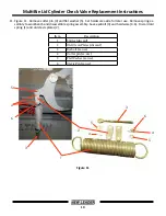
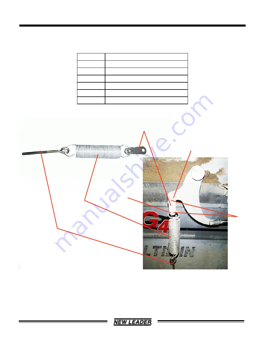
12. Figure 12 - Install original spring eyebolt (3) and new longer clevis plates (2) onto new spring (1), reusing 

original hardware (4-6).  Install new spring assembly using original clevis pin (6), cotter pin (4), and wash-

er(5).

Item

Description

1

New Spring

2

New longer Clevis plates

3

Eyebolt (re-use)

4

Cotter pin (re-use)

5

Flat Washer (re-use)

6

Clevis Pin (re-use)

Figure 12

1

2

3

4

5

6

Summary of Contents for MultiBin

Page 1: ... measures to prevent falling or runaway of cylinder or mechanism before maintenance and restart of spreader Exhaust all residual air and cut the pressure supply for components before servicing Injury can occur if precautions are not taken Follow this procedure to replace re install the MultiBin Lid cylinder check valve See Figure 1 for list of parts in upgrade kit Item Description Quantity Tools N...

Page 2: ... Instructions 1 Drain air system and cycle lid control valve to expel any trapped air 2 Figure 2 Remove 4 cylinder guard retaining bolts 2 Set guard 1 and bolts 2 aside for later use Item Description 1 Cylinder guard 2 Retaining bolts Figure 2 1 2 2 ...

Page 3: ... Figure 3A Carefully clean area around all 4 air tubes 1 2 Unhook air supply tubes to cylinder 1 and air tubes between cylinder fittings 2 as shown in Figure 3B Item Description 1 Air Supply Tube 2 Air Cylinder Tube 3 Cylinder Fitting Figure 3A Figure 3B 1 2 3 3 3 ...

Page 4: ...Check Valve Replacement Instructions 4 Figure 4 Remove e clip 1 and clevis pin 2 from each end of cylinder Remove cylinder Set clevis pins and e clips aside for later use Item Description 1 E clip 2 Clevis Pin Figure 4 1 1 2 2 ...

Page 5: ...scard old fittings 2 6 Figure 6 Slide new check valve assembly 3 midway onto cylinder 1 Position as shown Note proper angle in Figure 6A Tighten hose clamps 4 Item Description 1 Cylinder 2 Old fittings 3 Check Valve Assembly 4 Hose Clamps Figure 5 Figure 6 1 2 1 4 3 Angle between 15 30 As viewed from Rod end of cylinder Figure 6A ...

Page 6: ...ons 7 Figure 7 Install new speed control fittings 2 onto cylinder 1 as shown Fittings do not require adjust ment for proper air flow NOTE Do NOT connect air tubes 3 at this time Item Description 1 Cylinder 2 Speed Control Fittings 3 Air Tubes Figure 7 3 1 2 2 ...

Page 7: ...placement Instructions 8 Figure 8 Reinstall cylinder as shown using original clevis pins 2 and e clips 1 NOTE Do NOT connect air tubes 3 at this time as shown in Figure 8 Item Description 1 E clip 2 Clevis Pin 3 Air Tubes Figure 8 1 1 2 2 3 ...

Page 8: ...s 9 Figure 9 By Hand open lid 1 to 20 and insert block 2 Assist spring 3 will be left at its shortest posi tion Item Description 1 Lid 2 Block 3 Assist Spring WARNING Block cover lid to prevent closing Unintentional closing could cause injury Figure 9 20 1 2 3 ...

Page 9: ...y remove eyebolt 3 8 nut 2 Set nut 2 and spring pivot 3 aside for later use CAUTION Eyebolt is under tension Caution should be used when removing to prevent parts from being thrown by spring Safety glasses should be worn when working on this component Item Description 1 Eyebolt 2 3 8 Nut 3 Spring Pivot Figure 10 1 2 3 ...

Page 10: ...for later use Remove spring as sembly to workbench and disassemble spring assembly Save eyebolt 3 and hardware 4 6 Discard old spring 1 and old clevis plates 2 Item Description 1 Spring discard 2 Old Clevis Plates discard 3 Eyebolt re use 4 Cotter pin re use 5 Flat Washer re use 6 Clevis Pin re use Figure 11 3 4 4 5 5 6 6 5 4 3 1 2 ...

Page 11: ...new longer clevis plates 2 onto new spring 1 reusing original hardware 4 6 Install new spring assembly using original clevis pin 6 cotter pin 4 and wash er 5 Item Description 1 New Spring 2 New longer Clevis plates 3 Eyebolt re use 4 Cotter pin re use 5 Flat Washer re use 6 Clevis Pin re use Figure 12 1 2 3 4 5 6 ...

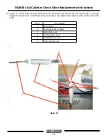
Page 12: ... Instructions 13 Figure 13 Use Vise Grips to secure eyebolt 1 Reinstall spring eyebolt using original spring pivot 3 and hardware Thread 3 8 nut 2 onto eyebolt ONLY 1 2 at this time Item Description 1 Eyebolt 2 3 8 Nut 3 Spring Pivot Figure 13 1 2 3 ...

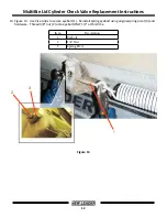
Page 13: ... Instructions 14 Figure 14 Remove block and lower lid Tension spring 1 to 16 1 4 as shown by adjusting eyebolt hard ware When spring is properly adjusted tighten the eyebolt jam nut 3 8 Nut 2 Item Description 1 Eyebolt 2 3 8 Nut Figure 14 16 1 4 1 2 ...

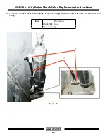
Page 14: ...r Check Valve Replacement Instructions 15 Figure 15 Connect check valve tubes 1 to cylinder fittings 2 at both ends Push firmly to seat tubes into fittings Item Description 1 Check Valve tube 2 Cylinder fitting Figure 15 2 1 ...

Page 15: ...th as needed and install into right hand check valve fitting 3 Clean original long tube 2 cut to length as needed and install into left hand check valve fitting 4 Push firmly to seat tubes into fittings Item Description 1 New 24 tube 2 Original long tube 3 Right hand check valve fitting 4 Left hand check valve fitting Figure 16 1 3 2 4 ...

Page 16: ...16 MultiBin Lid Cylinder Check Valve Replacement Instructions 17 Figure 17 Reinstall cylinder guard 1 and 4 guard retaining bolts 2 Item Description 1 Cylinder guard 2 Retaining bolts Figure 17 1 2 2 ...

Page 17: ...nt Instructions 18 Figure 18 On right hand front corner of spreader remove air supply tube 3 from control valve inlet fitting 2 on control valve assembly 1 Item Description 1 Control valve assembly 2 Inlet fitting 3 Air Supply tube Figure 18 1 3 2 ...

Page 18: ...stall new inline air filter 5 with corrugated tube 4 into inlet fitting 2 on control valve as sembly 1 Push firmly to seat tube 3 into fitting Item Description 1 Control valve assembly 2 Inlet fitting 3 Short Air Supply tube 4 Corrugated tube 5 Inline filter Figure 19 1 2 3 4 5 ...

Page 19: ...embly 1 Push firmly to seat tube into filter Slide corrugated tube 2 over inline filter Item Description 1 Control valve assembly 2 Corrugated tube 3 Inline filter 4 Air Supply Tube Figure 20 21 Start engine and allow air pressure to build in system Test operation by cycling lid control valve several times and check for air leaks Lid will open and close smoothly for correct operation 1 2 3 4 ...

Reviews: