background image

14

110839-01 - 8/20

AP-U

Installation & Service Manual

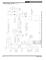
Figure 3-5:  Schematic Tankless Heater Piping

Table 3-6:  Tankless Heater Ratings

dishwashers and automatic washers is 

possible by piping the hot water from the 

heater prior to entering the mixing valve. The 

mixing valve should be “trapped” by installing 

it below the cold water inlet to heater to prevent 

lime formation in the valve.  Refer to Figure 3-5.

3.  FLUSHING OF HEATER — All water contains 

some sediment which settles on the inside of 

the coil. Consequently, the heater should be 

periodically backwashed. This is accomplished 

by installing hose bibs as illustrated and 

allowing water at city pressure to run into hose 

bib A, through the heater, and out hose bib B 

until the discharge is clear. The tees in which 

the hose bibs are located should be the same 

size as heater connections to minimize 

pressure drop.

4.  HARD WATER  — A water analysis is 

necessary to determine the hardness of your 

potable water. This is applicable to some city 

water and particularly to well water. An 

appropriate water softener should be installed 

based on the analysis and dealer’s 

recommendation. This is not only beneficial to 

the tankless heater but to piping and fixtures 

plus the many other benefits derived from soft 

water.

Boiler Model

Tankless Heater Model

S-5A

GPM

PSID

AP-110U-T

15

AP-154U-T

25

3

 Water Piping and Trim 

(continued)

THE FOLLOWING GUIDELINES SHOULD BE 

FOLLOWED WHEN PIPING THE TANKLESS HEATER: 

1.  FLOW REGULATION — If flow through the 

heater is greater than its rating, the supply of 

adequate hot water may not be able to keep 

up with the demand. For this reason a flow 

regulator matching the heater rating should be 

installed in the cold water line to the heater. 

The flow regulator should preferably be located 

below the inlet to the heater and a minimum of 

3’ away from the inlet so that the regulator is 

not subjected to excess temperatures that may 

occur during “off” periods when it is possible 

for heat to be conducted back through the 

supply line. The flow regulator also limits the 

flow of supply water regardless of inlet 

pressure variations in the range of 20 to 125 

psi.

2.  TEMPERING OF HOT WATER — Installation of 

an automatic mixing valve will lengthen the 

delivery of the available hot water by mixing 

some cold water with the hot. This prevents the 

possibility of scalding hot water at the fixtures. 

In addition, savings of hot water will be 

achieved since the user will not waste as much 

hot water while seeking a water temperature. 

Higher temperature hot water required by 

Summary of Contents for AP-U AP-110U-N

Page 1: ...call your heating contractor When seeking information on boiler provide Boiler Model Number and Serial Number as shown on Rating Label Installation Operating and Service Instructions for Manual Conten...

Page 2: ...NSI NFPA 31 Installation of Oil Burning Equipment for recommended installation practices Burning Equipment for recommended installation practices B Current Edition of American National Standard ANSI N...

Page 3: ...stall Limit Sensor may result in property damage personal injury or loss of life due to elevated operating temperatures and or pressures This boiler is NOT suitable for installation on combustible flo...

Page 4: ...proved chimney or vent system in good condition Serious property damage could result if the boiler is connected to a dirty or inadequate chimney or vent system The interior of the chimney flue must be...

Page 5: ...ler Dimensional Data Boiler Model Number Dimension A Water Capacity gallons Approx Shipping Weight lb AP 110U N T 34 9 16 10 1 300 AP 154U N T 41 15 4 355 Note Maximum Working Pressure Water 30 PSI sh...

Page 6: ...H MBH 1 Round In Dia Rectangle In x In Height Ft AP 110U N T 0 75 110 95 83 86 2 6 8 x 8 15 AP 154U N T 1 10 154 139 117 86 0 6 8 x 8 15 1 MBH refers to thousands of BTU per hour 2 Based on Standard T...

Page 7: ...TALLATION provide a solid elevated base such as concrete if floor is not level or if water may be encountered on floor around boiler WARNING DO NOT support boiler by placing blocks at the four 4 corne...

Page 8: ...on 5 For boiler located in a confined space or an unconfined space in a building of unusually tight construction provide outdoor air with the use of two permanent openings which communicate directly o...

Page 9: ...indicated in Figure 2 2 These dimensions will assure that the boiler jacket will be at least 18 from the side and rear walls and 48 from the front wall as required by ANSI NFPA 31 3 Fasten shield to c...

Page 10: ...o supply sufficient flow GPM to allow a 20 F temperature differential in the system When sizing the system circulator the pressure drop of all radiators baseboard and radiant tubing and all connecting...

Page 11: ...ve is installed as shown in Figure 5 Safety relief valve discharge piping must be piped near floor to eliminate potential of severe burns DO NOT pipe in any area where freezing could occur DO NOT inst...

Page 12: ...12 110839 01 8 20 AP U Installation Service Manual Figure 3 3 Recommended Boiler Piping for Circulator Zoned Heating Systems Supply Side Circulator 3Water Piping and Trim continued...

Page 13: ...13 110839 01 8 20 AP U Installation Service Manual Figure 3 4 Boiler Piping for Zone Valve Zoned Heating Systems Supply Side Circulator 3Water Piping and Trim continued...

Page 14: ...heater but to piping and fixtures plus the many other benefits derived from soft water Boiler Model Tankless Heater Model S 5A GPM PSID AP 110U T 3 15 AP 154U T 3 25 3Water Piping and Trim continued...

Page 15: ...fuel to be burned and sends less heat up the chimney A new boiler probably has a higher efficiency than the boiler being replaced That probably means that the stack temperature from the new boiler wil...

Page 16: ...16 110839 01 8 20 AP U Installation Service Manual Figure 4 1 Recommended Smokepipe Arrangement and Chimney Requirements Figure 4 2 Draft Regulator Locations 4Venting continued...

Page 17: ...large furniture away from thermostat so there will be free movement of room air around this control Connect the thermostat to the T T terminals on the control WARNING The maximum allowable current for...

Page 18: ...18 110839 01 8 20 AP U Installation Service Manual Figure 5 1 Schematic Wiring Diagram 5 Electrical continued...

Page 19: ...19 110839 01 8 20 AP U Installation Service Manual 5 Electrical continued Figure 5 2 Schematic Wiring Diagram...

Page 20: ...mpression fittings 4 Use of a high efficiency micron filter Garber or equivalent in addition to conventional filter is highly recommended Figure 6 1 Single Pipe Installation B SINGLE PIPE OIL LINES 1...

Page 21: ...llation Lift H See Figure Maximum Length of Tubing H R See Figure 3 8 OD Tubing 3 GPH 1 2 OD Tubing 3 GPH 0 84 100 1 78 100 2 73 100 3 68 100 4 63 100 5 57 100 6 52 100 7 47 100 8 42 100 9 36 100 10 3...

Page 22: ...epeat this step until all zones have been purged At completion open all zone valves i Close purge valve continue filling the system until the pressure gauge reads 12 psi Close shut off valve in cold w...

Page 23: ...ary see Burner Specifications Table 7 1 2 BECKETT AFG BURNERS This Beckett AFG burner is equipped with a non adjustable Fixed F Series Head the number is stamped on the head a Remove Gun Assembly b Ve...

Page 24: ...RESET BUTTON on Oil Primary Control and release 3 READJUST THE AIR DAMPER SETTING air Band Air Shutter Air Gate on the burner for a light orange colored flame while the draft over the fire is 0 02 Us...

Page 25: ...n of all boiler controls must be checked particularly the primary control and high limit control 2 VERIFY OIL PRIMARY CONTROL FEATURES using procedures outlined in Instructions furnished with control...

Page 26: ...flame present see chart below Flame Detection Range Normal 0 1600 ohms Limited 1600 ohms to lockout 3 CHECK OIL PRIMARY CONTROL CAUTION Due to the potential hazard of line voltage only a trained exper...

Page 27: ...hest setting b Allow burner to run until boiler water temperature exceeds high limit setting The burner should shut down and circulators continue running c Allow the temperature to drop below control...

Page 28: ...Recommended setting for Four zone systems 5 Recommended setting for Five zone systems HI Provides highest level of fuel savings E Optional Features NOTE The Program Mode Pro is accessed by turning th...

Page 29: ...tting the Well Type Elctro Well vs Standard Immersion Well When used to replace older temperature only controls the HyrdroStat can be installed on the existing well The Hydrolevel Elctro Well is requi...

Page 30: ...3 Push the Test Setting Button to Y to reset all features to the default settings 4 Reset LO TEMP and HI TEMP settings to desired temperatures 9 LED Legend and Test Settings Button a TEMP ACTIVE Indi...

Page 31: ...Smart HydroStat will reduce boiler temperature to conserve fuel The Economy feature is activated using the ECONOMY dial See How Thermal Targeting Works for more information f ECONOMY TARGET When the...

Page 32: ...on paper is inexpensive and obtainable from any chemical supply house or through your local druggist The pH should be higher than 7 but lower than 11 Add some of the washout chemical caustic soda if n...

Page 33: ...urner is shut down for an extended period of time 5 To recondition the heating system in the fall season after a prolonged shut down follow the instructions outlined in Section VII System Start Up Par...

Page 34: ...EAN THE FIRETUBES a Disconnect electric to burner and remove stack b For access to the firetubes pull top jacket panel off Remove brass nuts that hold canopy down Without taking off carriage bolts pul...

Page 35: ...ter as a minimum 2 Long sleeved loose fitting clothing 3 Gloves 4 Eye Protection Dampen RCF to be removed with light water spray to prevent fibers from becoming airborne Take steps to assure adequate...

Page 36: ...ect an air leak can have on CO2 readings 5 DIRT A fuel filter is a good investment Accidental accumulation of dirt in the fuel system can clog the nozzle or nozzle strainer and produce a poor spray pa...

Page 37: ...or relay is stuck closed see note below 2 Burner control will light then shut down after a short time then restart after one 1 minute a CAD cell is defective b Air leaking into oil line causing flame...

Page 38: ...are illuminated and the control is installed on a standard immersion well this is false reading caused by a loss of continuity between the sensor and the inside of the well tube Follow steps 1 and 2 a...

Page 39: ...ll times when the control is powered Check for 120 VAC on terminals L1 and L2 YES Is the Red LED LOW WATER On YES NO Is the Yellow LED HI TEMP On YES The Control is Sensing High Temperature The burner...

Page 40: ...ntinue to fire when there is a call from the thermostat or external zone Is the External Zone ZC ZR Calling for Heat YES The Control is Operating Normally NO Is the Low Limit Dial NO Set to OFF Check...

Page 41: ...41 110839 01 8 20 AP U Installation Service Manual This page intentionally left blank...

Page 42: ...utor Should you require assistance in locating a New Yorker distributor in your area or have questions regarding the availability of New Yorker products or service parts please contact New Yorker Boil...

Page 43: ...110840 01 1 S 301 110841 01 1 1B Base Assembly 110842 01 1 1 1C Canopy Includes Cerafelt Strips and Hardware 110843 01 1 1 1D Turbulator Kit S 101 110844 01 16 S 301 110845 01 16 1E Combustion Chamber...

Page 44: ...Installation Service Manual NOTE Whenorderingpartsalwaysgivetheserialnumberandmodelnumbershownontheboiler Alsoprovidethe name of the part s shown below Figure 12 2 Service Parts Jacket and Trim 12 Se...

Page 45: ...e 105894 01 1 1 2D Limit Hydrolevel HydroStat 3250 Plus Non Heater 110849 01 1 1 Heater 110850 01 1 1 2E Electro Well 3 4 NPT x 4 110556 01 1 1 Not Shown Taco 007e Obtain Locally 1 1 Relief Valve Conb...

Page 46: ...46 110839 01 8 20 AP U Installation Service Manual SERVICE RECORD SERVICE PERFORMED DATE...

Page 47: ...47 110839 01 8 20 AP U Installation Service Manual SERVICE RECORD SERVICE PERFORMED DATE...

Page 48: ...48 110839 01 8 20 AP U Installation Service Manual...

Reviews: