background image

106213-01- 11/15

9700609

Price - $5.00

For service or repairs to boiler, call your heating contractor.  When seeking information on boiler, 

provide Boiler Model Number and Serial Number as shown on Rating Label.
Boiler Model Number
   CG _ _ E


 Boiler Serial Number

  Installation Date

Heating Contractor

  Phone Number

Address

INSTALLATION, OPERATING

AND

SERVICE INSTRUCTIONS

CG-E™ SERIES

GAS BOILER

BEFORE INSTALLATION: READ THIS MANUAL

SAVE THESE INSTRUCTIONS

Installing contractor and homeowner should read and be informed as to the proper installation and operation of this boiler. 

The manufacturer will not be responsible for improper installation or operation. This manual and all associated instruction 

material should be conspicuously posted near the boiler.

Summary of Contents for CG-E SERIES

Page 1: ...eating Contractor Phone Number Address INSTALLATION OPERATING AND SERVICE INSTRUCTIONS CG E Series GAS BOILER BEFORE INSTALLATION READ THIS MANUAL SAVE THESE INSTRUCTIONS Installing contractor and hom...

Page 2: ...n or maintenance which are important but not related to personal injury hazards The City of New York requires a Licensed Master Plumber supervise the installation of this product The Massachusetts Boa...

Page 3: ...ments 120VAC 60 Hz 1 ph Less than 12A Maximum Allowable Working Pressure 50 psi Boiler shipped from factory with a 30 psi relief valve Boiler Model Input MBH 1 Shipping Weight lbs Empty Weight lbs Wat...

Page 4: ...4 Figure 1 Minimum Clearance to Combustible Materials and Alcove Dimensions...

Page 5: ...if floor is not level or if water may be encountered on floor around boiler CAUTION ASSURE THAT THE FRONT AIR DAM is in place and undamaged A damaged front air dam will negatively affect the performan...

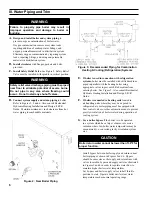
Page 6: ...t be installed with chilled medium piped in parallel with the heating boiler using appropriate valves to prevent chilled medium from entering boiler See Figure 3 Also consult Residential Hydronic Heat...

Page 7: ...according to the LWCO manufacturer s instructions 2 The recommended location for a LWCO on gas hot water boilers is above the boiler in the supply piping The minimum safe water level of a water boile...

Page 8: ...8 Figure 5 Recommended Water Piping for Zone Valve Zoned Heating Systems...

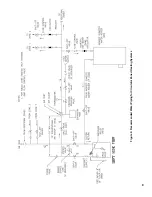
Page 9: ...9 Figure 6 Recommended Water Piping for Circulator Zoned Heating Systems...

Page 10: ...tile lining will cause severe injury or death B Inspect chimney and remove any obstructions or restric tions Clean chimney if previously used for solid or liquid fuel burning appliances or fireplaces...

Page 11: ...e of a match or candle or smoke from a cigarette cigar or pipe f After it has been determined that each appliance remain ing connected to the common venting system properly vents when tested as outlin...

Page 12: ...pe resistant to action of liquefied petroleum gas V Gas Piping Figure 8 Pilot and Gas Piping 3 Install sediment trap ground joint union and manual shut off valve upstream of boiler gas control valve S...

Page 13: ...than 12 amperes A separate electrical circuit must be run from the main electrical service with an over current device disconnect in the circuit A service switch is recommended and may be required by...

Page 14: ...14 Figure 9 Wiring Connection Diagram...

Page 15: ...15 Figure 10 Schematic Ladder Diagram...

Page 16: ...16 Figure 11 Wiring Schematic Zone Valves Figure 12 Wiring Schematic Zone Circulators...

Page 17: ...main burners has been off for at least five minutes and vent damper has been in the open position 4 Turn OFF the electric switch serving boiler 5 Open valve on main gas line at meter 6 Purge air from...

Page 18: ...18 Figure 14 Operating Instructions...

Page 19: ...should not be confused with true yellow tipping E Check Pilot Burner Flame 1 See Figure 16 The pilot burner should be lit only if thermostat is calling for heat The pilot burner produces three 3 flam...

Page 20: ...at call for heat is wired to the DHW input the control starts the circulator and if the boiler temperature is less than the operating setpoint less differential the vent damper is energized without de...

Page 21: ...ial Setpoint when outdoor sensor installed The Outdoor Reset Differential Setpoint is user adjustable by turning the bottom knob labeled OUTDOOR RESET DIFF Adjustment range is 0 F to 50 F When no outd...

Page 22: ...respirator 2 Long sleeved loose fitting clothing 3 Gloves 4 Eye Protection Take steps to assure adequate ventilation Wash all exposed body areas gently with soap and water after contact Wash work clo...

Page 23: ...ire plug at the gas valve d Remove wires to flame roll out switch e Remove the burner access panel f Mark the location of the pilot main burner on the manifold if the marking on manifold is missing or...

Page 24: ...on when the harness is reconnected Table 3 Troubleshooting Using the Control s LED Flashing LED Fault Condition POWER Steady 1 Hz flash Flash code 2 Flash code 3 Flash code 4 Flash code 5 Flash code 6...

Page 25: ...adjust thermostat or remove wire from TT terminals Check for 24Vac between P6 5 and ground If voltage not present attempt to start boiler again If 24Vac is present unplug the vent damper harness from...

Page 26: ...by a collapsed chimney resulting in full or partial blockage chimney cross sectional area too small height insufficient or cold chimney causing sustained poor draft Always follow the recommendations...

Page 27: ...rculator is On But Damper is Not Open LED Status Recommended Corrective Action POWER TSTAT CIRC LIMIT Damper Failed to Open The control is waiting for the damper to open Damper end switch has failed t...

Page 28: ...as flow check the following 24 volts across PV and MV PV at gas valve if voltage ok replace defective gas valve Check for break in wiring harness to gas valve 24 volts across control connector P4 6 an...

Page 29: ...rea or have questions regarding the availability of New Yorker products or repair parts please contact New Yorker Boiler Company Inc P O Box 10 Hatfield Pennsylvania 19440 0010 Attn Customer Service D...

Page 30: ...y Complete 102287 03 1 102287 04 1 102287 05 1 102287 06 1 102287 07 1 102287 08 1 102287 09 1 1B Canopy Gasket Kit 6201001 1 1 1 1 1 1 1 1C Canopy Assembly 102254 03 1 102254 04 1 102254 05 1 102254...

Page 31: ...31 Section Assembly and Canopy Group...

Page 32: ...ssembly 61807031 1 61807041 1 61807051 1 61807061 1 61807071 1 61807081 1 61807091 1 2D Base Front Panel 102705 03 1 102705 04 1 102705 05 1 102705 06 1 102705 07 1 102705 08 1 102705 09 1 2E Burner A...

Page 33: ...7042 1 72007052 1 72007062 1 72007072 1 72007082 1 72007092 1 2K Base Leg Assembly 6186001 4 4 4 4 4 4 4 2L Flame Roll out Switch 80160044 1 1 1 1 1 1 1 2M Manifold Support Bracket 718070001 1 1 1 1 1...

Page 34: ...1 82207051 1 82207061 1 82207071 1 82207081 1 82207091 1 3C Main Burner Orifice 47 White Nat Gas 822710 4 6 8 10 12 14 16 3C Main Burner Orifice 1 20 mm LP 822792 4 6 8 10 12 14 16 3D Main Burner w 60...

Page 35: ...rol Atmospheric Draft UTEC 1135 630 106541 01 1 1 1 1 1 1 1 4B Transformer 40 VA modified Honeywell AT140B1297 106529 01 1 1 1 1 1 1 1 4C Limit Rated Temperature Sensor 12 Lg Tasseron 106643 01 1 1 1...

Page 36: ...6 Key No Description Part Number CG E MODEL 30 40 50 60 70 80 90 Jacket Assembly Complete 5 Jacket Assembly Complete 106707 03 1 106707 04 1 106707 05 1 106707 06 1 106707 07 1 106707 08 1 106707 09 1...

Page 37: ...1 1 1 1 1 1 1 6C Safety Relief Valve 30 psi 81660363 1 1 1 1 1 1 1 6D Drain Valve 102802 01 1 1 1 1 1 1 1 6E Vent Damper 4 Dia 102284 01 1 Vent Damper 5 Dia 102284 02 1 Vent Damper 6 Dia 102284 03 1 1...

Page 38: ...38...

Page 39: ...39...

Page 40: ...40...

Reviews: