2
The following terms are used throughout this manual to bring attention to the presence of hazards of various
risk levels, or to important information concerning product life.
DANGER
Indicates an imminently hazardous situation
which, if not avoided, will result in death, serious
injury or substantial property damage.
CAUTION
Indicates a potentially hazardous situation which,
if not avoided, may result in moderate or minor
injury or property damage.
WARNING
Indicates a potentially hazardous situation which,
if not avoided, could result in death, serious injury
or substantial property damage.
NOTICE
Indicates special instructions on installation,
operation, or maintenance which are important
but not related to personal injury hazards.
The City of New York requires a Licensed Master Plumber supervise the installation of this product.
The Massachusetts Board of Plumbers and Gas Fitters has approved the CG-E™ Series Boiler. See the Massachusetts Board of
Plumbers and Gas Fitters website,
http://license.reg.state.ma.us/pubLic/pl_products/pb_pre_form.asp
for the latest Approval
Code or ask your local Sales Representative.
The Commonwealth of Massachusetts requires this product to be installed by a licensed Plumber or Gas fitter.
Table of Contents
I. Pre-Installation ....................................5
II. Unpack Boiler .....................................5
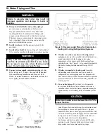
III. Water Piping and Trim ........................6
IV. Venting ..............................................10
V. Gas Piping .........................................12
VI. Electrical ............................................13
VII. System Start-up and Checkout .....................17
VIII. Operation ..........................................20
IX. Service and Maintenance ...................22
X. Troubleshooting ................................24
XI. Repair Parts .......................................29
Warranty .............................Back Cover
Summary of Contents for CG-E SERIES
Page 4: ...4 Figure 1 Minimum Clearance to Combustible Materials and Alcove Dimensions...
Page 8: ...8 Figure 5 Recommended Water Piping for Zone Valve Zoned Heating Systems...
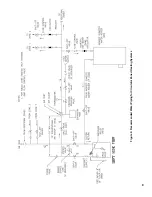
Page 9: ...9 Figure 6 Recommended Water Piping for Circulator Zoned Heating Systems...
Page 14: ...14 Figure 9 Wiring Connection Diagram...
Page 15: ...15 Figure 10 Schematic Ladder Diagram...
Page 16: ...16 Figure 11 Wiring Schematic Zone Valves Figure 12 Wiring Schematic Zone Circulators...
Page 18: ...18 Figure 14 Operating Instructions...
Page 31: ...31 Section Assembly and Canopy Group...
Page 38: ...38...
Page 39: ...39...
Page 40: ...40...


