28
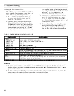
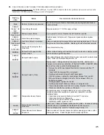
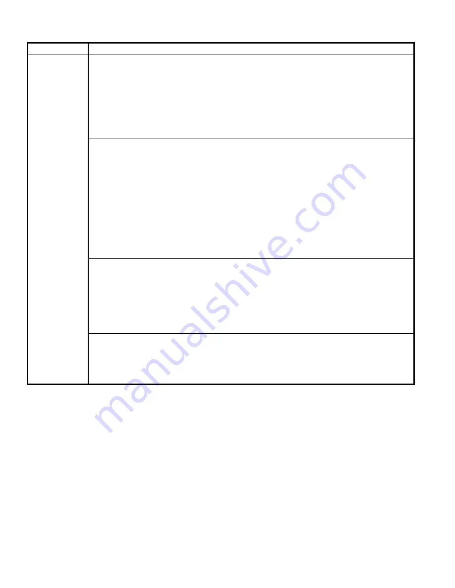
LED / Status
Recommended Corrective Action
- POWER
- TSTAT/CIRC
- LIMIT
- DAMPER
Retry / Recycle
Delay
1. No Spark
a. Can you hear sparking?
- If there is no spark noise replace the control.
b. If you can hear spark noise check the following:
- Loose connection in ignition cable or ground wire
- Continuity of ignition cable
- Break in ignition cable insulation
- Loose ground connection
- Break in pilot ceramic insulator
- Incorrect pilot spark gap
2. No Pilot Flame
a. If pilot does not light check the following:
- All manual gas valves are open
- Supply tubing is not plugged, kinked or leaking
- Gas line pressures are good
- Gas line is purged of air
- Pilot orifice is not plugged (pilot gas is flowing)
- Condensate quenching pilot
Note
: It may be necessary to recycle the “call for heat” more than once to clear the pilot supply tubes
of air.
b. If no gas flow check the following:
- 24 volts across PV and MV/PV at gas valve, if voltage ok replace defective gas valve
- Check for break in wiring harness to gas valve
- 24 volts across control connector P4-6 and P4-7, if no voltage at control replace defective control
3. Spark does Not Stop When Pilot Lights
If the spark does not stop when the pilot lights check the following:
- Loose connection in ignition cable or ground wire
- Continuity of ignition cable
- Clean flame rod
- Pilot electrode porcelain cracked
- Pilot flame covers flame rod and is steady and blue, if not adjust pilot flame
- Low gas pressure at gas valve inlet
- Defective control
4. Main Flame Does Not Light
If the main burners do not light check the following:
- Check orifice size and/or blockage
- 24 volts across control terminals P4-5 and P4-7? If no voltage while in defective control.
- 24 volts across MV and MV/PV at gas valve? Check for break in wiring harness to gas valve
- Defective gas valve
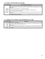
5. Circulator is On, Damper is Open But Boiler Fails to Start (continued)
Summary of Contents for CG-E SERIES
Page 4: ...4 Figure 1 Minimum Clearance to Combustible Materials and Alcove Dimensions...
Page 8: ...8 Figure 5 Recommended Water Piping for Zone Valve Zoned Heating Systems...
Page 9: ...9 Figure 6 Recommended Water Piping for Circulator Zoned Heating Systems...
Page 14: ...14 Figure 9 Wiring Connection Diagram...
Page 15: ...15 Figure 10 Schematic Ladder Diagram...
Page 16: ...16 Figure 11 Wiring Schematic Zone Valves Figure 12 Wiring Schematic Zone Circulators...
Page 18: ...18 Figure 14 Operating Instructions...
Page 31: ...31 Section Assembly and Canopy Group...
Page 38: ...38...
Page 39: ...39...
Page 40: ...40...


