background image

4


Recommended service clearance is 24 inches from 

left side, right side and front. Service clearances may 

be reduced to minimum clearances to combustible 

materials.

E.


Install on level floor.

 For basement installation provide 

concrete base if floor is not level or if water may be 

encountered on floor around boiler.

F.


Protect gas ignition system components

 from water 

(dripping, spraying, rain, etc.) during boiler operation 

and service (circulator replacement, condensate trap, 

control replacement, etc.).

G.


Provide combustion and ventilation air

 in accordance 

with applicable provisions of local building codes, 

or National

 Fuel Gas Code

, NFPA 54/ANSI Z223.1, 

Section 5.3, Air for Combustion and Ventilation.

G

N

I

N

R

A

W

r

i

a

n

o

i

t

a

li

t

n

e

v

d

n

a

n

o

i

t

s

u

b

m

o

c

e

t

a

u

q

e

d

A

r

e

p

o

r

p

e

r

u

s

s

a

o

t

d

e

d

i

v

o

r

p

e

b

t

s

u

m

.

n

o

i

t

s

u

b

m

o

c


The following guideline is based on the 

National Fuel 

Gas Code

, NFPA 54/ANSI Z223.1.

1.  Determine volume of space (boiler room). Rooms 

communicating directly with space (through 

openings not furnished with doors) are considered 

part of space.

  Volume [ft³] = Length [ft] x Width [ft] x Height [ft]
2.  Determine Total Input of all appliances in space. 

Round result to nearest 1,000 Btu per hour (Btuh).

3.  Determine type of space. Divide Volume by Total 

Input.
a.  If result is greater than or equal to 50 ft³ per 

1,000 Btuh, space is considered an 

unconfined 

space

.

b.  If result is less than 50 ft³ per 1,000 Btuh, space 

is considered a 

confined space

.

4.  Determine building type. A building of 

unusually 

tight construction

 has the following characteristics:

a.  Walls and ceiling exposed to outside atmosphere 

have a continuous water vapor retarder with a 

rating of 1 perm or less with openings gasketed 

and sealed, and;

b.  Weather-stripping has been added on openable 

windows and doors, and;

c.  Caulking or sealants applied in joints around 

window and door frames, between sole 

plates and floors, between wall-ceiling joints, 

between wall panels, at plumbing and electrical 

penetrations, and at other openings.

5.  For boiler located in an 

unconfined space in a 

building of


other than unusually tight construction

adequate combustion and ventilation air is normally 

provided by fresh air infiltration through cracks 

around windows and doors.

6.  For boiler located within 

unconfined space in 

building of unusually tight construction

 or within 

confined space

, provide outdoor air through two 

permanent openings which communicate directly or 

by duct with the outdoors or spaces (crawl or attic) 

freely communicating with the outdoors. Locate one 

opening within 12 inches of top of space. Locate 

remaining opening within 12 inches of bottom of 

space. Minimum dimension of air opening is 3 

inches. Size each opening per following:
a.  Direct communication with outdoors. Minimum 

free area of 1 square inch per 4,000 Btu per hour 

input of all equipment in space.

b.  Vertical ducts. Minimum free area of 1 square 

inch per 4,000 Btu per hour input of all 

equipment in space. Duct cross-sectional area 

shall be same as opening free area.

c.  Horizontal ducts. Minimum free area of 1 

square inch per 2,000 Btu per hour input of all 

equipment in space. Duct cross-sectional area 

shall be same as opening free area.


Alternate method for boiler located within confined 

space.

 Use indoor air if two permanent openings 

communicate directly with additional space(s) of 

sufficient volume such that combined volume of all 

spaces meet criteria for unconfined space. Size each 

opening for minimum free area of 1 square inch per 

1,000 Btu per hour input of all equipment in spaces, 

but not less than 100 square inches.

7.  Ventilation Duct Louvers and Grilles. Equip outside 

openings with louvers to prevent entrance of rain 

and snow, and screens to prevent entrance of insects 

and rodents. Louvers and grilles must be fixed in 

open position or interlocked with equipment to open 

automatically before burner operation. Screens must 

not be smaller than ¼ inch mesh.

  Consider the blocking effect of louvers, grilles and 

screens when calculating the opening size to provide 

the required free area. If free area of louver or grille 

is not known, assume wood louvers have 20-25 

percent free area and metal louvers and grilles have 

60-75 percent free area.

H

.


Do not install boiler where gasoline

 or other 

flammable vapors or liquids, or sources of 

hydrocarbons (i.e. bleaches, cleaners, chemicals, sprays, 

paint removers, fabric softeners, etc.) are used or stored.

Summary of Contents for Classic CGS-A Series

Page 1: ... the boiler INSTALLATION OPERATING AND SERVICE INSTRUCTIONS Classic CGS A Series GAS BOILER n o n o i t a m r o f n i g n i k e e s n e h W r o t c a r t n o c g n i t a e h r u o y l l a c r e l i o b o t s r i a p e r r o e c i v r e s r o F l e b a L g n i t a R n o n w o h s s a r e b m u N l a i r e S d n a r e b m u N l e d o M r e l i o B e d i v o r p r e l i o b r e b m u N l e d o M r e ...

Page 2: ...O N n o i t a l l a t s n i n o s n o i t c u r t s n i l a i c e p s s e t a c i d n I e r a h c i h w e c n a n e t n i a m r o n o i t a r e p o y r u j n i l a n o s r e p o t d e t a l e r t o n t u b t n a t r o p m i s d r a z a h N O I T U A C n o i t a u t i s s u o d r a z a h y l l a i t n e t o p a s e t a c i d n I n i t l u s e r y a m d e d i o v a t o n f i h c i h w y t r e p o r ...

Page 3: ...pment B Installation must conform to the requirements of the authority having jurisdiction In the absence of such requirements installation must conform to National Fuel Gas Code NFPA 54 ANSI Z223 1 Where required by the authority having jurisdiction the installation must conform to the Standard for Controls and Safety Devices for Automatically Fired Boilers ANSI ASME CSD 1 C Boiler is design cert...

Page 4: ...ight construction adequate combustion and ventilation air is normally provided by fresh air infiltration through cracks around windows and doors 6 For boiler located within unconfined space in building of unusually tight construction or within confined space provide outdoor air through two permanent openings which communicate directly or by duct with the outdoors or spaces crawl or attic freely co...

Page 5: ... materials in distribution system Eliminate oxygen contamination by repairing system leaks repairing fittings and using nonpermeable materials in distribution system II Unpack Boiler Figure 3 Special Base Installation B Boiler equipped with McDonnell Miller 67 Low Water Cutoff Only Assemble gauge glass and low water cutoff as shown in Figure 5 Follow instructions packed with low water cutoff 1 Aff...

Page 6: ...a T e z i S e s o p r u P A 2 y l p p u S d n o c e S l a n o i t p O d e g g u l P 0 7 0 3 y l p p u S d n o c e S 0 8 B o t d e h s u b e g u a G e r u s s e r P C O C W L t a o l F s s a l G e g u a G D 2 d r a d n a t S n r u t e R E e v l a V y t e f a S F 2 e v l a V n i a r D e t a n r e t l A n r u t e R G 2 y l p p u S H t i m i L K f f o t u C r e t a W w o L e b o r P O C W L 7 6 r e l ...

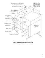
Page 7: ... Figure 7 Recommended Boiler Piping for Gravity Return ...

Page 8: ...ons other than those listed above refer to National Fuel Gas Code NFPA 54 ANSI Z223 1 or size system using standard engineering methods acceptable to authority having jurisdiction B Connect boiler gas valve to gas supply system 1 Use methods and materials in accordance with local plumbing codes and requirements of gas supplier In absence of such requirements follow National Fuel Gas Code NFPA 54 A...

Page 9: ... u s s e r P c w h c n i 3 0 p o r D e r u s s e r P c w h c n i 5 0 1 1 1 1 0 1 2 3 1 8 7 2 0 2 5 0 5 0 1 5 7 1 0 6 3 0 8 6 0 0 4 1 0 2 2 9 0 9 1 0 5 3 0 3 7 0 2 1 0 5 2 5 6 4 0 5 9 0 3 3 7 2 5 1 5 8 2 0 9 5 7 9 0 0 2 5 7 3 0 7 7 0 4 3 6 0 3 1 5 4 2 0 0 5 2 8 0 7 1 0 2 3 0 6 6 0 5 6 5 5 1 1 5 1 2 0 4 4 3 7 1 5 1 5 8 2 0 8 5 0 6 0 5 5 0 1 5 9 1 0 0 4 6 6 8 3 1 0 6 2 0 3 5 0 7 6 4 6 9 0 8 1 0 7 3 1...

Page 10: ...Install Draft Hood without modification on outlet of flue collector See Figure 1 Secure with sheet metal screws G N I N R A W y n a e c a l p r o d o o h t f a r d r e l i o b r e t l a t o n o D e h t n i r e p m a d d e v o r p p a n o n r o n o i t c u r t s b o e g a l l i p s s a g e u l F m e t s y s t n e v r o g n i h c e e r b e m o c e b l l i w n o i t a c i f i t r e c A G A r u c c o ...

Page 11: ... Damper Installation G N I N R A W s i h t e s u d n a l l a t s n i y l r e p o r p o t e r u l i a F y t r e p o r p n i t l u s e r y a m h c t i w S t n e V d e k c o l B e f i l f o s s o l r o y r u j n i l a n o s r e p e g a m a d E Install Vent Damper See Figure 11 1 Open Vent Damper Carton and remove Installation Instructions Read Installation Instructions thoroughly before proceeding E ...

Page 12: ...e the other appliances remaining connected to the common venting system are not in operation a Seal any unused openings in the common venting system b Visually inspect the venting system for proper size and horizontal pitch and determine there is no blockage or restriction leakage corrosion and other deficiencies which could cause an unsafe condition c Insofar as is practical close all building do...

Page 13: ... 13 Vent Damper Schematic Wiring Diagram Table 8 Wiring Diagrams F Wire boiler Boiler is rated for 120 VAC 60 hertz less than 12 amperes Provide individual branch circuit with fused disconnect Connect to black and white wires and green ground screw Install Transformer on Junction Box G Vent Damper Sequence of Operation See Figure 13 1 Vent Damper continuously powered at Terminal 1 2 Call for heat ...

Page 14: ... flame and causes gas valve to turn off main burner and pilot burner gas flow should pilot burner flame extinguish Vent Damper remains open with call for heat H Sequence of Operation Continuous Ignition Standing Pilot 1 Normal Operation a Thermostat calls for heat Vent Damper opens b Gas Valve energized allowing main gas flow and ignition of Main Burners c Call for heat ends Gas Valve de energized...

Page 15: ...t for one minute Vent Damper remains open with call for heat For Electronic Ignition Troubleshooting Guide see Pages 26 27 I Sequence of Operation with Intermittent Ignition EI 1 Normal Operation a Thermostat calls for heat Vent Damper opens b Ignition Module energized Pilot Valve opens Igniter energized to ignite Pilot Burner c Sensor proves presence of pilot flame Main Valve opens and ignites Ma...

Page 16: ...enses pilot flame and causes gas valve to turn off main burner and pilot burner gas flow should pilot burner flame extinguish Vent Damper remains open with call for heat L Sequence of Operation Continuous Ignition Standing Pilot 1 Normal Operation a Thermostat calls for heat Vent Damper opens b Gas Valve energized allowing main gas flow and ignition of Main Burners c Call for heat ends Gas Valve d...

Page 17: ...blockage must be corrected by trained and skilled personnel from a qualified service agency before resetting switch d Flame Roll out Switch Automatically interrupts boiler operation when flames or excessive heat are present in vestibule Vent Damper remains open with call for heat Control is single use device If flame roll out switch is activated do not attempt to place boiler in operation The sour...

Page 18: ... piping and connections between Gas Valve and Manifold orifices and pilot tubing while boiler is operating Locate leaks using approved combustible gas detector soap and water or similar nonflammable solution Do not use matches candles open flames or other ignition source Figure 18 Pilot Burner Flame Continuous Ignition H Check pilot burner flame 1 Continuous Ignition standing pilot See Figure 18 P...

Page 19: ...r p e r a c t e t s u d l l a w r e n r u b e h t s n o i t i d n o c e s e h t r e d n u d e t a r e p o d n a d e n a e l c e b t s u m s t r o p d n a r o i r e t n i n o i t a r e p o r e p o r p e r u s n i o t y l i a d d e t c e p s n i s d n o c e S e n O r o f n o i t u l o v e R l a i D r e t e M s a G f o e z i S f l a H e n O t F u C e n O t F u C o w T t F u C e v i F t F u C 0 3 0 6 ...

Page 20: ...pilot or Figure 22 for intermittent ignition EI Adjust thermostat to normal setting 4 Determine Input Rate Multiply gas flow rate by gas heating value 5 Compare measured input rate to input rate listed on rating label a Boiler must not be overfired Reduce input rate by decreasing manifold pressure Do not reduce more than 0 3 inch w c If boiler is still overfired contact New Yorker Boiler Company f...

Page 21: ...ot or Figure 22 for intermittent ignition EI Remove manometer 5 Follow Lighting or Operating Instructions to place boiler in operation See Figure 21 for continuous ignition standing pilot or Figure 22 for intermittent ignition EI Adjust thermostat to normal setting Q Clean Heating System Oil from new piping connections and sediment in existing piping must be removed from the system to prevent unst...

Page 22: ...e boiler in operation See Figure 21 for continuous ignition standing pilot or Figure 22 for intermittent ignition EI 3 Operate boiler at this water level for at least 30 minutes after the condensate begins to run hot 4 Follow instructions TO TURN OFF GAS TO APPLIANCE See Figure 21 for continuous ignition standing pilot or Figure 22 for intermittent ignition EI 5 Close all radiator valves Remove al...

Page 23: ...ready to be put into service U Combustion Chamber Burn off 1 The mineral wool combustion chamber panels contain a cornstarch based binder that must be burned out a installation to prevent odors during subsequent boiler operation 2 Ventilate the boiler room set the high limit to its maximum setting set the thermostat to call for heat Allow the boiler to fire for at least an hour or until the odor f...

Page 24: ...r Cutoff McDonnell Miller 67 Only 1 Weekly or more frequently if necessary Open blow off valve to flush sediment chamber Follow instructions on Blow Down Card affixed to Jacket adjacent to low water cutoff 2 Annual Dismantle to extent necessary to remove obstructions and insure proper function of working parts a Inspect connecting lines to boiler for accumulation of mud and scale Clean as necessar...

Page 25: ... c Disconnect Flame Rollout Switch wires d Remove Burner Access Panel e Lift front of burner to clear orifice and lift burner out Burner which holds pilot can only be removed by lifting at a 45 angle after burner adjacent to its right is removed 2 Brush top of burners with a soft bristle brush See Figure 24 Vacuum burners 3 Check orifices Drilled passageways must be free of lint or dirt Figure 25 ...

Page 26: ...26 ELECTRONIC IGNITION TROUBLE SHOOTING GUIDE ...

Page 27: ...27 ...

Page 28: ... n a C 3 0 2 1 1 1 6 1 4 0 2 1 1 1 6 1 5 0 2 1 1 1 6 1 6 0 2 1 1 1 6 1 7 0 2 1 1 1 6 1 8 0 2 1 1 1 6 1 8 8 x 2 x 2 1 p i r t S g n i l a e S t l e f a r e C e s a B o t y l b m e s s A n o i t c e S 1 7 0 7 1 0 2 7 1 1 1 1 1 1 t e k c a r B e c i f i r O d e t t o l S w r e n r u B n i a M 9 1 1 6 3 2 8 3 4 6 9 1 1 4 1 d n a t e k c a r B t o l i P 0 5 3 Q 0 7 h t i w r e n r u B n i a M n o i t i...

Page 29: ...8 R V l l e w y e n o H e v l a V s a G 3 8 1 0 6 6 1 8 1 1 e n a p o r P P L 0 4 0 6 C 0 0 3 8 R V l l e w y e n o H e v l a V s a G 3 4 2 0 6 6 1 8 1 1 1 1 e n a p o r P P L 8 4 5 4 C 0 0 3 8 R V l l e w y e n o H e v l a V s a G 4 4 2 0 6 6 1 8 1 1 6 6 9 1 A 9 0 3 Q l l e w y e n o H 6 3 e l p u o c o m r e h T 4 0 0 6 3 2 8 1 8 8 9 1 A 9 0 3 Q l l e w y e n o H 0 3 e l p u o c o m r e h T 4 2 ...

Page 30: ...e m r o f s n a r T 1 0 0 1 1 0 7 1 1 1 1 1 1 h c t i w S t u o l l o R e m a l F 4 4 0 0 6 1 0 8 1 1 1 1 1 1 y l b m e s s A t n e m e c a l p e R h c t i w S t n e V d e k c o l B 6 6 0 6 1 0 6 1 1 1 1 1 1 r e t a W w o L o t u C l o r t n o C d n a e b o r P 0 0 4 5 4 l e v e l o r d y H f f 5 2 6 0 6 1 0 8 1 1 1 1 1 1 C r e t a W w o L o t u 2 0 8 S P r e l l i M l l e n n o D c M f f l o r t ...

Page 31: ... Long sleeved loose fitting clothing 3 Gloves 4 Eye Protection Take steps to assure adequate ventilation Wash all exposed body areas gently with soap and water after contact Wash work clothes separately from other laundry and rinse washing machine after use to avoid contaminating other clothes Discard used RCF components by sealing in an airtight plastic bag RCF and crystalline silica are not clas...

Page 32: ...associated controls 6 Geographic Limitations These warranties apply only to boilers installed within the 48 contiguous United States 7 Installation Requirements In order for these warranties to be effective a The boiler must be installed in a single or two family residential dw This warranty does not apply to boilers installed in apart elling ments or for commercial or industrial applications b Th...

Reviews: