18
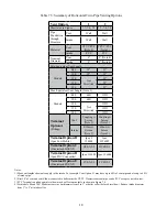
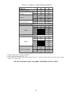
Table 7.5: Summary of Horizontal Twin Pipe Venting Options
Vent Option
1
2
Illustrated in Figure
7.7, 7.8, 7.9 7.7, 7.8, 7.9
Pipe
Penetration
through
Structure
Vent
Wall
Wall
Intake
Wall
Wall
Material
Vent
CPVC/PVC
(Note 2)
CPVC/PVC
(Note 2)
Intake
PVC
PVC
Nominal
Diameter
Vent
2”
3” (Note 4)
Intake
2”
3” (Note 4)
Min Equivalent Vent Length:
Models
080
12”
12”
100
12”
12”
120
Not
Permitted
12”
150
52”
180
52”
Max Equivalent Vent Length (Note 1):
Models
080
60ft
135ft
100
60ft
135ft
120
Not
Permitted
135ft
150
135ft
180
135ft
Terminal
Option A
(Fittings)
Vent
Coupling w
Screen
(Note 3)
Coupling w
Screen
(Note 3)
Intake
Elbow w
Screen
(Note 3)
Elbow w
Screen
(Note 3)
Terminal Option B
(Ipex Low Profile)
Ipex #
196984
Ipex
#196985
Terminal Option C
(Diversitech HVENT)
HVENT-2
HVENT-3
Terminal Option D
(Ipex FGV Concentric)
Ipex 196105 Ipex 196006
Terminal Option E
(Diversitech CVENT)
CVENT-2
CVENT-3
Notes:
1) Max vent lengths shown also apply to the intake. For example, Vent Option #1 may have up to 60ft of vent pipe and also up to 60 ft
of intake pipe.
2) First 30” of vent and vent Elbow connected to boiler must be CPVC. Downstream vent pipe can be PVC except as noted in text.
3) PVC Terminal coupling and inlet elbow may be offset on snorkels as shown in Figure 7.6.
4) For models 80 and 100: Make increase in vent diameter from 2 to 3” at boiler collar (before first elbow). Reduce intake diameter
from 3” to 2” at intake collar.
Summary of Contents for GHE Series
Page 10: ...9 Figure 5 1 Wall Layout Mounting Hole Location...
Page 11: ...10 Figure 5 2 Boiler Mounting Bracket Installation Boiler Wall Mounting...
Page 17: ...16 FIGURE 7 4 WALL PENETRATION CLEARANCES FOR PVC VENT PIPE...
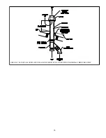
Page 34: ...33 FIGURE 7 24 INSTALLATION OF IPEX AND DIVERSITECH CONCENTRIC TERMINAL THROUGH ROOF...
Page 41: ...40 FIGURE 9 2 NEAR BOILER PIPING HEATING ONLY BOILER LOOP PIPING SHOWN SHADED...
Page 42: ...41 FIGURE 9 3a NEAR BOILER PIPING HEATING PLUS INDIRECT WATER HEATER...
Page 43: ...42 FIGURE 9 3b NEAR BOILER PIPING HEATING PLUS INDIRECT WATER HEATER...
Page 47: ...46 This page is intentionally left blank...
Page 50: ...49 FIGURE 10 2 LINE VOLTAGE FIELD CONNECTIONS FIGURE 10 3 LOW VOLTAGE PCB TERMINAL CONNECTIONS...
Page 52: ...51 FIGURE 10 4a 120V LWCO FIELD WIRING FIGURE 10 4b 24V LWCO FIELD WIRING...
Page 54: ...53 FIGURE 10 6 INTERNAL WIRING CONNECTIONS DIAGRAM...
Page 55: ...54...
Page 62: ...61 Lighting and Operating Instructions...
Page 82: ...81 FIGURE 14 6 CONTROLS LOCATION FIGURE 14 7 PRESSURE SWITCH TUBING CONNECTIONS...
Page 87: ...86 Blower Gas Valve Assembly for 150 180...
Page 90: ...89...
Page 103: ...102...


