27
E. Assembly of CPVC/PVC Vent Systems
WARNING
• Asphyxiation Hazard. Failure to follow these instructions could cause products of combustion to
enter the building, resulting in severe property damage, personal injury, or death.
• A CPVC elbow and a 30” straight section of CPVC (not supplied) must be installed at the boiler
end of the vent system before transitioning to Schedule 40 PVC pipe (ASTM 2665) components for
remainder of vent system.
• Use CPVC vent components within any interior space where air cannot circulate freely, including
through vertical or horizontal chase ways, inside a stud wall, in closets and through wall
penetrations.
• The use of cellular core PVC (ASTM F891), cellular core CPVC or Radel (polyphenolsulfone is
prohibited.
• All condensate that forms in the vent must be able to drain back to the boiler.
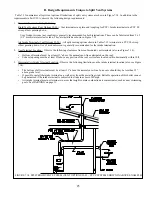
• Never leave the boiler in operation without the gas sample cap in place (Figure 7.17)
1. Assemble the vent system, starting at the boiler:
a. A CPVC elbow and a 30” straight section of CPVC (not supplied) must be used before transitioning to PVC. If
necessary the 30” straight section of CPVC may be cut in any location and the CPVC elbow inserted between the
two resulting segments.
b. When cutting CPVC or PVC pipe, use a miter saw or a saw designed to cut PVC pipe. Use a miter box or other
method to cut pipe squarely. De-burr both the inside and outside of the cut end.
c.
Dry fit all vent components before assembly.
d.
Lubricate the upper gasket in the vent adaptor with water and insert the first piece of CPVC into the vent adaptor
until it bottoms out. Tighten the gear clamp on the adapter.
e.
Assemble the CPVC elbow and the remainder of the 30” CPVC piping before transitioning to PVC. The first piece
of PVC will either be connected to the CPVC elbow or the end of a section of CPVC vent pipe. In the latter case, a
PVC coupling may be used to connect the first piece of PVC to the last piece of CPVC.
f. Clean all CPVC and PVC components with the appropriate primer before cementing. Cement the vent system
together, starting at the boiler and following the instructions provided on the cans of cement and primer. Use a
field supplied cement and primer that is listed for use with the materials being joined (CPVC and/or PVC). The
following, or its equivalent, may be used to join CPVC to PVC:
•
IPS Corporation #P-70 Primer
•
IPS Corporation #790 Multi-Purpose Solvent Cement
Always use primer on both the pipe and fitting before applying the cement. Assemble the pipe in accordance with
the instructions on the cans of primer and cement.
g. Assemble the rest of the vent system, being sure to pitch horizontal sections back towards the boiler 1/4”/ft. Support
the vent at intervals not exceeding 4ft.
h. Maintain the clearances from the vent pipe outlined in Part VII-A of this manual. If exiting the exterior wall using
PVC pipe, use half of an appropriately sized wall thimble (or a sheet metal plate) on the exterior of the building, to
provide a weather tight seal while maintaining the proper clearance in the wall penetration. Seal the joint between
the pipe and the wall plate using RTV applied on the exterior side of the wall. This sealant must not restrain the
expansion of the vent pipe.
2. Installation of Air Intake System - Start assembly of the PVC air intake system at the boiler. Assembly of the air intake
system is done in the same manner as the vent system except as follows:
a.
Drill a 7/32” clearance hole into the front side of the air intake adapter. Insert the first piece of PVC air intake pipe
into the air intake connection and drill a 1/8” tap hole into the PVC which lines up with the 7/32” clearance hole and
secure them together with a #10 x 1” sheet metal screw. Seal the joint between the intake pipe and the adaptor with
RTV.
b. All intake piping may be PVC.
c. There is a 0” minimum clearance between the air intake piping and all types of construction.
d. To the extent possible, pitch horizontal air intake piping towards the outdoors.
3. Installation of Horizontal Fitting Terminals (Terminal Option A):
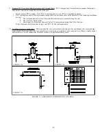
a. See Figure 7.18 for proper orientation of twin pipe horizontal terminals. Outer edge of both terminals must be
within 10” from wall surface. (Figure 7.7)
Summary of Contents for GHE Series
Page 10: ...9 Figure 5 1 Wall Layout Mounting Hole Location...
Page 11: ...10 Figure 5 2 Boiler Mounting Bracket Installation Boiler Wall Mounting...
Page 17: ...16 FIGURE 7 4 WALL PENETRATION CLEARANCES FOR PVC VENT PIPE...
Page 34: ...33 FIGURE 7 24 INSTALLATION OF IPEX AND DIVERSITECH CONCENTRIC TERMINAL THROUGH ROOF...
Page 41: ...40 FIGURE 9 2 NEAR BOILER PIPING HEATING ONLY BOILER LOOP PIPING SHOWN SHADED...
Page 42: ...41 FIGURE 9 3a NEAR BOILER PIPING HEATING PLUS INDIRECT WATER HEATER...
Page 43: ...42 FIGURE 9 3b NEAR BOILER PIPING HEATING PLUS INDIRECT WATER HEATER...
Page 47: ...46 This page is intentionally left blank...
Page 50: ...49 FIGURE 10 2 LINE VOLTAGE FIELD CONNECTIONS FIGURE 10 3 LOW VOLTAGE PCB TERMINAL CONNECTIONS...
Page 52: ...51 FIGURE 10 4a 120V LWCO FIELD WIRING FIGURE 10 4b 24V LWCO FIELD WIRING...
Page 54: ...53 FIGURE 10 6 INTERNAL WIRING CONNECTIONS DIAGRAM...
Page 55: ...54...
Page 62: ...61 Lighting and Operating Instructions...
Page 82: ...81 FIGURE 14 6 CONTROLS LOCATION FIGURE 14 7 PRESSURE SWITCH TUBING CONNECTIONS...
Page 87: ...86 Blower Gas Valve Assembly for 150 180...
Page 90: ...89...
Page 103: ...102...


