64
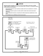
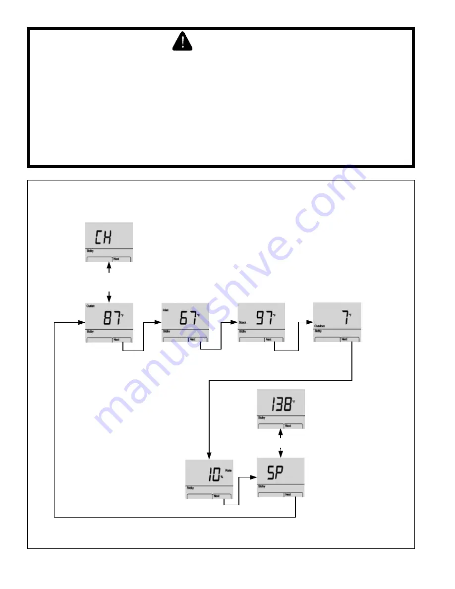
Alternate
Flash
(If
Demand
Present)
Alternate
Flash
Code
for
Current
Demand:
CH
=
Space
Heat
dH
=
Domestic
Hot
Water
FP
=
Frost
Protection
Press
RH
Button
(“Next”)
to
advance
through
screens
Current
set
point
(shown
for
CH
if
no
demand
present)
Home
Screen
Shows
Outlet
(Supply)
Temp
Inlet
(Return)
Temp
Stack
Temp
Outdoor
Temp
(Screen
skipped
if
Odr
is
Off)
Current
%
of
High
Fire
Fan
Speed
FIGURE 12.1: USER MODE SCREENS
WARNING
Burn Hazard. Water temperatures over 125°F can cause personal injury or death due to scalding.
Children, Disabled, and Elderly are at most risk of being scalded. This boiler is not designed to directly
control domestic water temperature.
• Use only the thermostat recommended by the indirect water heater manufacture to control the
DHW temperature.
• Adjust the thermostat set point in accordance with the indirect water heater manufacturer’s
instructions.
• Install scald protection devices as required by the indirect water heater manufacturer or local
codes.
• Do not attempt to wire a DHW sensor into the boiler control.
Summary of Contents for GHE Series
Page 10: ...9 Figure 5 1 Wall Layout Mounting Hole Location...
Page 11: ...10 Figure 5 2 Boiler Mounting Bracket Installation Boiler Wall Mounting...
Page 17: ...16 FIGURE 7 4 WALL PENETRATION CLEARANCES FOR PVC VENT PIPE...
Page 34: ...33 FIGURE 7 24 INSTALLATION OF IPEX AND DIVERSITECH CONCENTRIC TERMINAL THROUGH ROOF...
Page 41: ...40 FIGURE 9 2 NEAR BOILER PIPING HEATING ONLY BOILER LOOP PIPING SHOWN SHADED...
Page 42: ...41 FIGURE 9 3a NEAR BOILER PIPING HEATING PLUS INDIRECT WATER HEATER...
Page 43: ...42 FIGURE 9 3b NEAR BOILER PIPING HEATING PLUS INDIRECT WATER HEATER...
Page 47: ...46 This page is intentionally left blank...
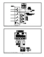
Page 50: ...49 FIGURE 10 2 LINE VOLTAGE FIELD CONNECTIONS FIGURE 10 3 LOW VOLTAGE PCB TERMINAL CONNECTIONS...
Page 52: ...51 FIGURE 10 4a 120V LWCO FIELD WIRING FIGURE 10 4b 24V LWCO FIELD WIRING...
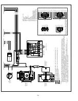
Page 54: ...53 FIGURE 10 6 INTERNAL WIRING CONNECTIONS DIAGRAM...
Page 55: ...54...
Page 62: ...61 Lighting and Operating Instructions...
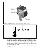
Page 82: ...81 FIGURE 14 6 CONTROLS LOCATION FIGURE 14 7 PRESSURE SWITCH TUBING CONNECTIONS...
Page 87: ...86 Blower Gas Valve Assembly for 150 180...
Page 90: ...89...
Page 103: ...102...


