80
FIGURE 14.5: TROUBLESHOOTING BLANK DISPLAY
START
Is
display
completely
dark?
Verify
that
display
is
not
still
in
power
‐
up
”
process
(Figure
11.2a)
Loose
or
mis
‐
wired
connection
between
the
display
and
terminal
J3
on
the
boiler
control
Defective
display
Is
boiler
control’s
green
power
light
on?
Is
boiler
fan
running
at
high
speed?
Is
120V
present
across
black
and
white
boiler
line
voltage
connection
leads?
Is
24VAC
present
between
J8
‐
1
and
J8
‐
2
(blue
and
yellow)
terminals
on
boiler
control?
Is
24VAC
present
across
transformer
secondary
(brown
and
pink
wires
at
plug
L3?)
Is
120VAC
present
across
black
and
white
wires
at
plug
L2?
Loose
or
mis
‐
wired
connection
between
the
display
and
terminal
J3
on
the
boiler
control
Defective
display
Open
fuse
or
breaker
at
main
panel
Loose
or
mis
‐
wired
connection
between
main
panel
and
boiler.
Defective
boiler
control
Loose
plug
L2
Defective
transformer
–
look
for
short
circuit
in
24V
wiring
Loose
plug
P1
Loose
plug
P3
Loose
connection
between
L3
and
J8
See
Figures
10.5
and
10.6
for
the
location
of
connectors
referenced
here
Y
N
Y
N
Y
N
Y
N
Y
N
Y
N
Y
N
Summary of Contents for GHE Series
Page 10: ...9 Figure 5 1 Wall Layout Mounting Hole Location...
Page 11: ...10 Figure 5 2 Boiler Mounting Bracket Installation Boiler Wall Mounting...
Page 17: ...16 FIGURE 7 4 WALL PENETRATION CLEARANCES FOR PVC VENT PIPE...
Page 34: ...33 FIGURE 7 24 INSTALLATION OF IPEX AND DIVERSITECH CONCENTRIC TERMINAL THROUGH ROOF...
Page 41: ...40 FIGURE 9 2 NEAR BOILER PIPING HEATING ONLY BOILER LOOP PIPING SHOWN SHADED...
Page 42: ...41 FIGURE 9 3a NEAR BOILER PIPING HEATING PLUS INDIRECT WATER HEATER...
Page 43: ...42 FIGURE 9 3b NEAR BOILER PIPING HEATING PLUS INDIRECT WATER HEATER...
Page 47: ...46 This page is intentionally left blank...
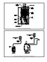
Page 50: ...49 FIGURE 10 2 LINE VOLTAGE FIELD CONNECTIONS FIGURE 10 3 LOW VOLTAGE PCB TERMINAL CONNECTIONS...
Page 52: ...51 FIGURE 10 4a 120V LWCO FIELD WIRING FIGURE 10 4b 24V LWCO FIELD WIRING...
Page 54: ...53 FIGURE 10 6 INTERNAL WIRING CONNECTIONS DIAGRAM...
Page 55: ...54...
Page 62: ...61 Lighting and Operating Instructions...
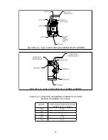
Page 82: ...81 FIGURE 14 6 CONTROLS LOCATION FIGURE 14 7 PRESSURE SWITCH TUBING CONNECTIONS...
Page 87: ...86 Blower Gas Valve Assembly for 150 180...
Page 90: ...89...
Page 103: ...102...


