94
7) Replace the screw cap in the vent adapter when combustion testing is complete.
8) Cycle boiler at least five times at the final throttle setting to ensure burner ignites without delay and without noise.
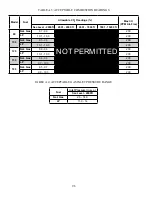
9) Verify that the gas inlet pressure is between the ranges shown in Table A.4 with all gas appliances (including the converted
boiler) both on and off.
10) A sheet of yellow labels is provided in the envelope with this manual for boilers converted from natural to LP gas. Select the
model from this sheet of labels and apply them as follows:
a. Apply the “Rating Plate Label” adjacent to the rating plate.
b. Apply the “Gas Valve Label” to a conspicuous area on the gas valve.
c. Apply the “Boiler Conversion Label” to a conspicuous surface on, or adjacent to, the outer boiler jacket. Fill in the
date of the conversion and the name and address of the company making the conversion with a permanent marker.
11) Refer to the “Start-up and Checkout” section of the boiler installation manual and perform any checks not already completed.
WARNING
• The throttle adjustments shown in Table A.2 are approximate. The final throttle setting must be
found using a combustion analyzer. Leaving the boiler in operation with a CO level in excess of
200PPM air-free could result in injury or death from carbon monoxide poisoning. Leaving the boiler
in operation with a CO
2
level outside of the range shown in Table A.3 could also result in injury or
death from carbon monoxide poisoning, even if the boiler is operating at an air-free CO level below
200PPM during this adjustment procedure.
• If the throttle is very far out of adjustment on the “rich” (counter-clockwise) side, the boiler
burner may be running at 0% excess air or even with air deficiency. Operating the boiler in this
condition may cause property damage, personal injury or loss of life. Under these conditions
most combustion analyzers used in the field will show 0% O
2
and a very high (well over 1000 ppm)
CO. Combustion readings will also appear to be unresponsive to throttle adjustment. If the boiler
appears to be operating under this condition, turn the throttle screw clockwise until the flame
lengthens significantly and is mostly blue. Then, slowly turn the throttle counter-clockwise, using a
combustion analyzer to achieve the required CO
2
as described in Step 6.
Summary of Contents for GHE Series
Page 10: ...9 Figure 5 1 Wall Layout Mounting Hole Location...
Page 11: ...10 Figure 5 2 Boiler Mounting Bracket Installation Boiler Wall Mounting...
Page 17: ...16 FIGURE 7 4 WALL PENETRATION CLEARANCES FOR PVC VENT PIPE...
Page 34: ...33 FIGURE 7 24 INSTALLATION OF IPEX AND DIVERSITECH CONCENTRIC TERMINAL THROUGH ROOF...
Page 41: ...40 FIGURE 9 2 NEAR BOILER PIPING HEATING ONLY BOILER LOOP PIPING SHOWN SHADED...
Page 42: ...41 FIGURE 9 3a NEAR BOILER PIPING HEATING PLUS INDIRECT WATER HEATER...
Page 43: ...42 FIGURE 9 3b NEAR BOILER PIPING HEATING PLUS INDIRECT WATER HEATER...
Page 47: ...46 This page is intentionally left blank...
Page 50: ...49 FIGURE 10 2 LINE VOLTAGE FIELD CONNECTIONS FIGURE 10 3 LOW VOLTAGE PCB TERMINAL CONNECTIONS...
Page 52: ...51 FIGURE 10 4a 120V LWCO FIELD WIRING FIGURE 10 4b 24V LWCO FIELD WIRING...
Page 54: ...53 FIGURE 10 6 INTERNAL WIRING CONNECTIONS DIAGRAM...
Page 55: ...54...
Page 62: ...61 Lighting and Operating Instructions...
Page 82: ...81 FIGURE 14 6 CONTROLS LOCATION FIGURE 14 7 PRESSURE SWITCH TUBING CONNECTIONS...
Page 87: ...86 Blower Gas Valve Assembly for 150 180...
Page 90: ...89...
Page 103: ...102...


