Setting Up The Unit
Error Compensation Setup
19
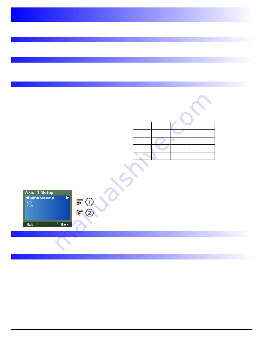
Signal Checking Setup
The DP1200 has the facility to detect if the encoder attached to the 4th digital axis has become
disconnected, sustained severe cable damage, or with some encoders, experienced electronic failure.
To enable Signal Checking
To disable Signal Checking
Zero Approach Setup
Please refer to Page 11, Zero Approach Setup
Please refer to Page 11, Error Compensation Explanation
Page 12, Type of Machine Error
Page 12, Linear Error Compensation Explanation
Page 13, Linear Compensation Setup
Direction Setup
Please refer to Page 10, Direction Setup
Radius / Diameter (Measure Setup)
Please refer to Page 10, Radius / Diameter (Measure Setup)
Mode of Operation
The detection mechanism monitors the incoming signals from the encoder to look for an illegal
combination of input levels.
If the encoder becomes disconnected, then the illegal
input combination is generated internally within the
DP1200. The display will then show ‘SIG FAIL’. If it is
possible to correct the fault, press the axis zero key to
reset that display. If the ‘SIG FAIL’ message continues
to be displayed then the fault has not been corrected.
A
B
RM
Status
L
L
H
SIG FAIL
L
H
X
OK
H
L
X
OK
X
X
L
OK
X = any state i.e can be either high (H) or low (L).
Note:
Please check the encoder specification for information on the synchronisation of the index
marker pulse. If the encoder is capable of generating the illegal condition (A low, B low and RM high),
then signal checking function should be
TURNED OFF
.
Summary of Contents for dp1200
Page 1: ...User Manual DP1200 Digital Readout...
Page 2: ......


