2.2 Power Supply
BEFORE CONNECTING THE ELECTRICAL SUPPLY TO THE CABINET, CHECK THAT THE VOLTAGE
SELECTOR SWITCH IS CORRECTLY SET. Figure 1.2 shows the position of this switch.
The mains supply is connected through a detachable supply cord. The cabinet is supplied with a cord fitted
with a right-angled connector. If another supply cord is to be used, it must have a IEC320, 10A, EARTHED
mains connector with a cord rated for at least 10A.
2.0 INSTALLATION
2.1 Mounting
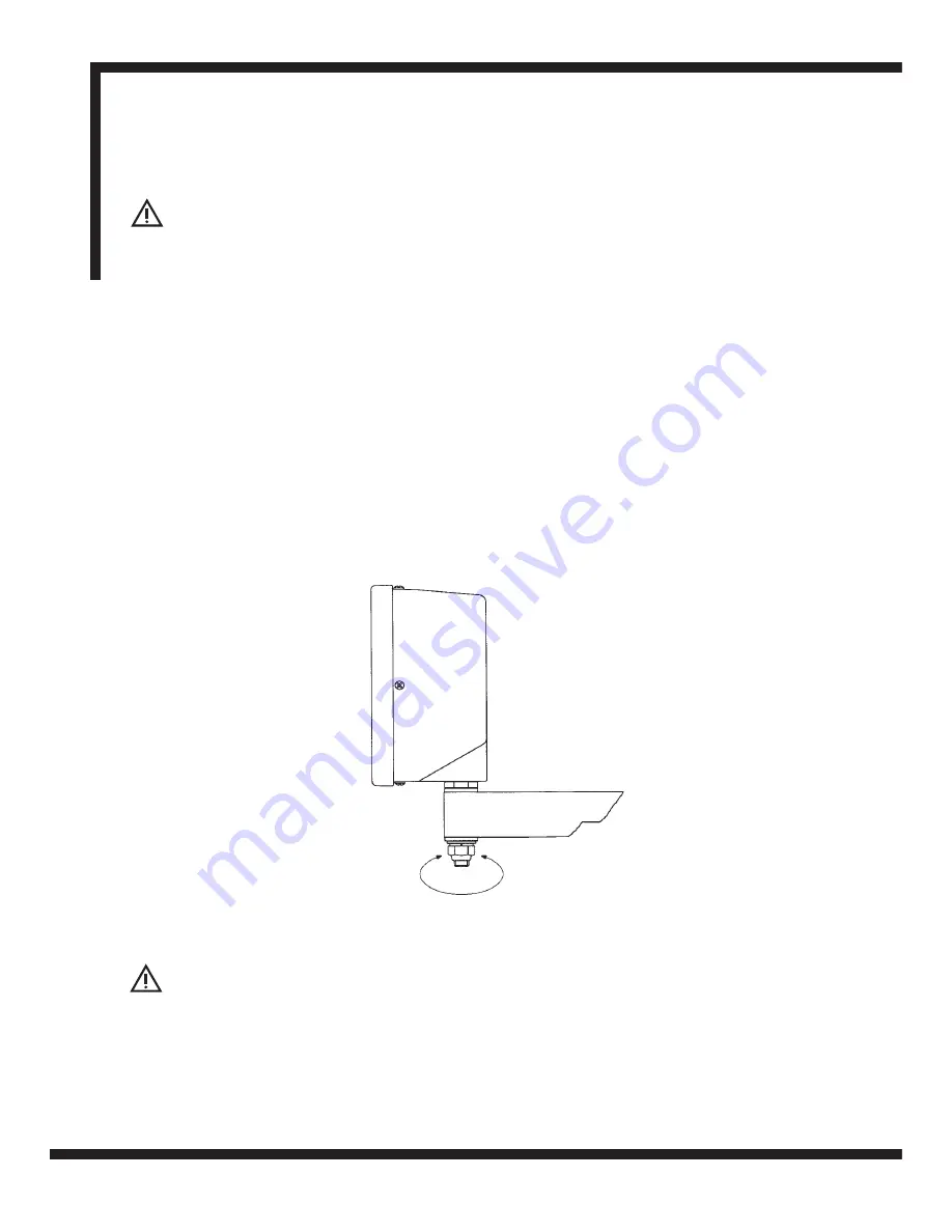
The DPG2000 is supplied with a fixing kit consisting of a M10 stud, nut and washers. Figure 1.1 shows the
use of this kit in conjunction with an optional mounting arm (Part No: 294-35670).
Be sure that the mounting arrangements are secure as the operator will need to apply pressure to the front
panel when using the keypad.
An optional mounting assembly (Part no: 294-37740) is available which allows for tilt and rotation of the
cabinet.
Select the location of the DPG2000 with due regard to safety and ease of operation. Keep clear of moving
parts and coolant spray. Ensure that the natural ventilation around the cabinet is not restricted.
To ensure correct operation of the DPG2000, it is recommended that the case is grounded to the machine.
Use a wire or strap of a least 1.5
mm
2
(16 AWG) from the cabinet equipotential terminal, (Figure 1.2), to a
suitable point on the machine body. The wire should be as short as possible. The machine must also be
properly grounded to a good earth point.
Installation
Newall Measurement Systems
3
Mounting Arm
Figure 1.1 Standard Fixing with Optional Mounting Arm


