Section-6
www.newavenergy.com
04-1206_S6_NW_OPMPS_10-50kVA_GB_110201.doc
Page 2/6
Printed in Switzerland – Modifications reserved
…
6.1 MULTI-CABINET
CONFIGURATION
6.1.1 CONCEPT OF MULTI-CABINET CONFIGURATION
The
POWERSCALE
UPS may be paralleled for power capacity or for redundancy up to 20 units. The standard
version is not provided with this feature which is optional and field upgradable.
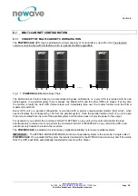
Fig. 1.1.
POWERSCALE
Multi-Cabinet Chain.
The Multi-Cabinet Chain is based on a decentralized bypass architecture i.e. every UPS is provided with its own
static bypass. In a parallel system there is always one Master UPS and the other UPSs are slaves. If at any time
the master is faulty the next UPS (former slave) will immediately take over the master function and the former
master will switch off.
Every UPS unit in a parallel configuration is provided with a proper output parallel Isolator (IA2) which, when
opened isolates the corresponding unit from the parallel system. Once the parallel isolator (IA2) of a unit is open
that unit is isolated from the rest of the parallel system and therefore does not provide power to the output.
For example if you perform the command “LOAD TO BYPASS” on any unit, all the units will transfer the load
simultaneously to mains and if you perform the command “LOAD TO INVERTER” on any unit all the UPS’s will
simultaneously transfer the load to the inverters.
The
POWERSCALE
is paralleled for redundancy (highest availability) or for power parallel systems.
IMPORTANT:
The BYPASS MODE (ECO-MODE) function of a parallel systems is the same as in single units of
POWERSCALE
. If in a parallel UPS system the load is transferred to the BYPASS (load on mains) and if the mains
fails, the UPS’s will all be automatically transferred to inverter within 5msec.


