background image

22 

unless these parts or devices will be permanently 
used in conjunction with the LRF device.  
- Turn on the LRF. 
- In the LRF menu select «SET», then «CAL». Press 
ACTION.  
- When the text «CALc» is shown, set the LRF 
horizontally on a flat surface, where the LRF will be 
rotated around vertical axis. Note: to achieve as 
accurate calibration results as possible, the digital 
compass should be exactly on the axis of rotation, 
please refer to the illustration below showing the 
location of the axis of rotation for this procedure.  
 
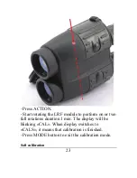
- Press the ACTION. -  -- Start rotating the LRF 
module to perform one or two full rotations duration 
1 min. The display will be blinking «CAL» during 
entire process. 
- When the display switches to «CALc», change 
LRF position to be on the left side down. Note: to 
achieve as accurate calibration results as possible, 
the digital compass should be exactly on the axis of 
rotation, please refer to the illustration below 
showing the location of the axis of rotation for this 
procedure. 
Summary of Contents for LRB 4000CI

Page 1: ...Operation Manual LRB 4000CI LASER RANGE FINDER BINOCULARS NSN 1240 20 001 9644 105 Sparks Ave Toronto ON M2H 2S5 Canada...

Page 2: ...VER aim the unit at the Sun or bright sources of light NEVER subject the unit to impacts NEVER transport the unit without its case NEVER disassemble the unit This may be hazardous for you due to high...

Page 3: ...fied herein may result in hazardous radiation exposure CAUTION use of optical instruments such as binoculars loupes mirrors lenses etc with this product increases eye hazard NOTE Avoid eye exposure to...

Page 4: ...ance 15 5 4 Target selection logic 16 5 5 Operation and service modes 18 5 6 Compass calibration 20 5 7 Distance accuracy correction 25 5 8 Setting interface format 26 5 9 Gating mode 26 5 10 Data Rec...

Page 5: ...f flight method of distance and speed measurement The System sends invisible eye safe laser pulses to the target The returned pulses are captured by the digital circuitry The time difference is used t...

Page 6: ...uisition Meters Yards Mils Degrees KMH MPH display Last 10 measurements recall Selectable reticle shape or Gating capability Speed detector Accurate digital compass Accurate digital inclinometer RS 23...

Page 7: ...VICE APPEARANCE 1 Eyepieces 2 Objective receiving lens 3 Objective emitting lens 4 Dioptric adjustment rings 5 Mode button 6 Action button 7 Body of the device 8 Rubber grip 2 3 4 5 6 7 1 8 Fig 1 Fron...

Page 8: ...7 1 Eyepiece 9 Interpupillary distance adjustment lever 10 Model Identification label 11 Identification and certification label on the bottom Fig 3 Label Fig 2 Rear view 11 10 9 1...

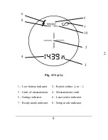
Page 9: ...w battery indicator 2 Reticle either or 3 Units of measurement 4 Measurement result 5 Gating indicator 6 Laser active indicator 7 Ready mode indicator 8 Setup mode indicator 4 6 2 1 3 10 8 Fig 4 Displ...

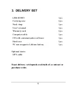
Page 10: ...ser s manual Warranty card Computer cable CD with communication software Hard case 9V non magnetic Lithium battery 1 pc 1 pc 1 pc 1 pc 1 pc 1 pc 1 pc 1 pc 1 pc Optional items GPS cable Exact delivery...

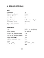
Page 11: ...y multi coated optics Interpupillary distance 58 72 mm Dioptre adjustment range 4 Range Finder Laser Class 1 eye safe 905 nm Measuring range 10 4000 m Accuracy and display resolution 1 m First last an...

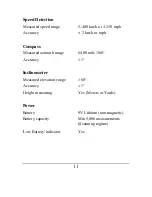
Page 12: ...m h or mph Compass Measured azimuth range 6400 mils 360 Accuracy 1 Inclinometer Measured elevation range 60 Accuracy 1 Height measuring Yes Meters or Yards Power Battery 9V Lithium non magnetic Batter...

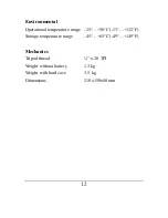
Page 13: ...ental Operational temperature range 25 50 C 13 122 F Storage temperature range 45 65 C 49 149 F Mechanics Tripod thread x 20 TPI Weight without battery 1 3kg Weight with hard case 3 5 kg Dimensions 21...

Page 14: ...nd evenly check that the battery snap wires are neatly packed inside the battery compartment and the cover is aligned over the edge of the battery compartment NOTE Battery in metal casing will diminis...

Page 15: ...ult form of Distance M Azimuth mils and Elevation mils measurement parameters also can be modified to user preference see Setup Mode If results of measurement are unreliable four dashes will be displa...

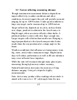
Page 16: ...ctive than a rough one Larger targets reflect better than small ones Ranging a target perpendicular to the laser beam provides better results than the one positioned at a sharp angle to the beam Weath...

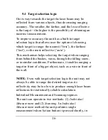
Page 17: ...echanism helps selecting the target when ranging from behind the bushes wires through the falling snow or in similar conditions Furthermore it enables ranging a target in front of a bigger object such...

Page 18: ...button is pressed Scanning or Individual Measurement regimes are available for any selected mode of measurement When two or more parameters are measured in Scanning regime though first result will be...

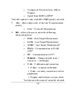
Page 19: ...ing modes of operation Ready Unit is ready to perform measurements dFLt sets default mode of operation with factory settings GAtE allows to set gating distance for measurement Std allows the user to s...

Page 20: ...ser to select the following advanced options o FrSt First Target Measurement o LASt Last Target Measurement o AUtO Last Target Measurement o PLGr Communication to PLGR GPS o PC Communication to PC o R...

Page 21: ...tached to the device were changed For example bracket made of magnetic metal was replaced or modified If calibration is performed only to improve accuracy of readings only the Elevation correction and...

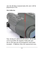
Page 22: ...rror will be proportional to the Hard calibration Note during all calibration procedures always put as far as possible all magnetic metal parts and devices that generate electromagnetic interference e...

Page 23: ...e axis of rotation please refer to the illustration below showing the location of the axis of rotation for this procedure Press the ACTION Start rotating the LRF module to perform one or two full rota...

Page 24: ...the LRF module to perform on or two full rotations duration 1 min The display will be blinking CAL When display switches to CALS it means that calibration is finished Press MODE button to exit the cal...

Page 25: ...he LRF shall be set horizontally and aim the LRF to the North 0 degrees press ACTION When the display shows C 90 the LRF shall be set horizontally and aim the LRF to the East 90 degrees press ACTION W...

Page 26: ...Corr from CAL menu Perform correction according to required measurement parameters by pressing Action button see table below Active mode of measurement Std Correction parameter Condition d Distance In...

Page 27: ...232 port in either PC format description of the proprietary format can be obtained from Newcon upon a request or in the format accepted by PLGF DALGR To select required data format Select PLGr or PC...

Page 28: ...distance click through full gating range with M button or hold M button for 2 seconds Gating feature helps measuring remote targets in unfavourable atmospheric and environmental conditions by eliminat...

Page 29: ...measurement results rEc 1 distance 1 azimuth 1 elevation 1 rEc 2 distance 2 azimuth 2 elevation 1 rEc 0 distance 0 azimuth 0 elevation 0 Measurement sets are numbered in reverse order first recalled s...

Page 30: ...ith both types is described in the manual Do not apply excessive force when disconnecting cable Damage to cable or connector resulting from improper handling is not covered by warranty To attach the c...

Page 31: ...CI can transmit the acquired data to a GPS receiver using DB15 connector and PLGR DAGR protocol An optional cable is required To work with GPS perform the following steps Choose dFLt measuring mode Sw...

Page 32: ...ute coordinates of your target NOTE If the rangefinder is not set initially to dFLt mode the GPS will not operate properly NOTE GPS unit automatically adjusts coordinates to reflect actual magnetic de...

Page 33: ...the stronger will be the reflection 3 The unit deploys sophisticated software that tries to understand which target you are aiming at However due to beam divergence several objects may produce a stro...

Page 34: ...n Gating provides better results than the last target selection but it requires preliminary rough distance estimation to cut off all objects closer than the chosen one NOTE Gating setting is remembere...

Page 35: ...rature Do not use the device at temperatures higher than 50o C 122o F Do not touch optical surfaces Doing so may damage the anti reflection coating Clean optical surfaces only with professional camera...

Page 36: ...splay may have small black dots scratches and other blemishes inherited from the manufacturing process These flaws are strictly regulated by number area and location and do not degrade the product s m...

Page 37: ...model the product or part thereof which on inspection by Newcon is found to be defective in materials or workmanship What This Warranty Does Not Cover NEWCON is not responsible for warranty service sh...

Page 38: ...am 5pm Monday Friday Eastern Standard Time At no time should equipment be sent back to Newcon without following the instructions of our technical support department NEWCON OPTIK accepts no responsibil...

Page 39: ...er __________________________________ The unit indicated above has passed the quality inspection Production date_________________________________ Quality Inspector________________________________ Purc...

Page 40: ...NEWCON OPTIK Printed in Canada R1 05 13...

Reviews: