Installation and commissioning
Manual DMT-TFT.110
15
4.2.1 Installation dimensions
Unless otherwise specified in the installation drawing: All tole/- 0.1 mm.
To allow cable installation, make sure that a gap of 5 mm to adjacent parts is provided on all four sides of the
DMT-TFT.110.
Provide additional space for the cables at connection X4.
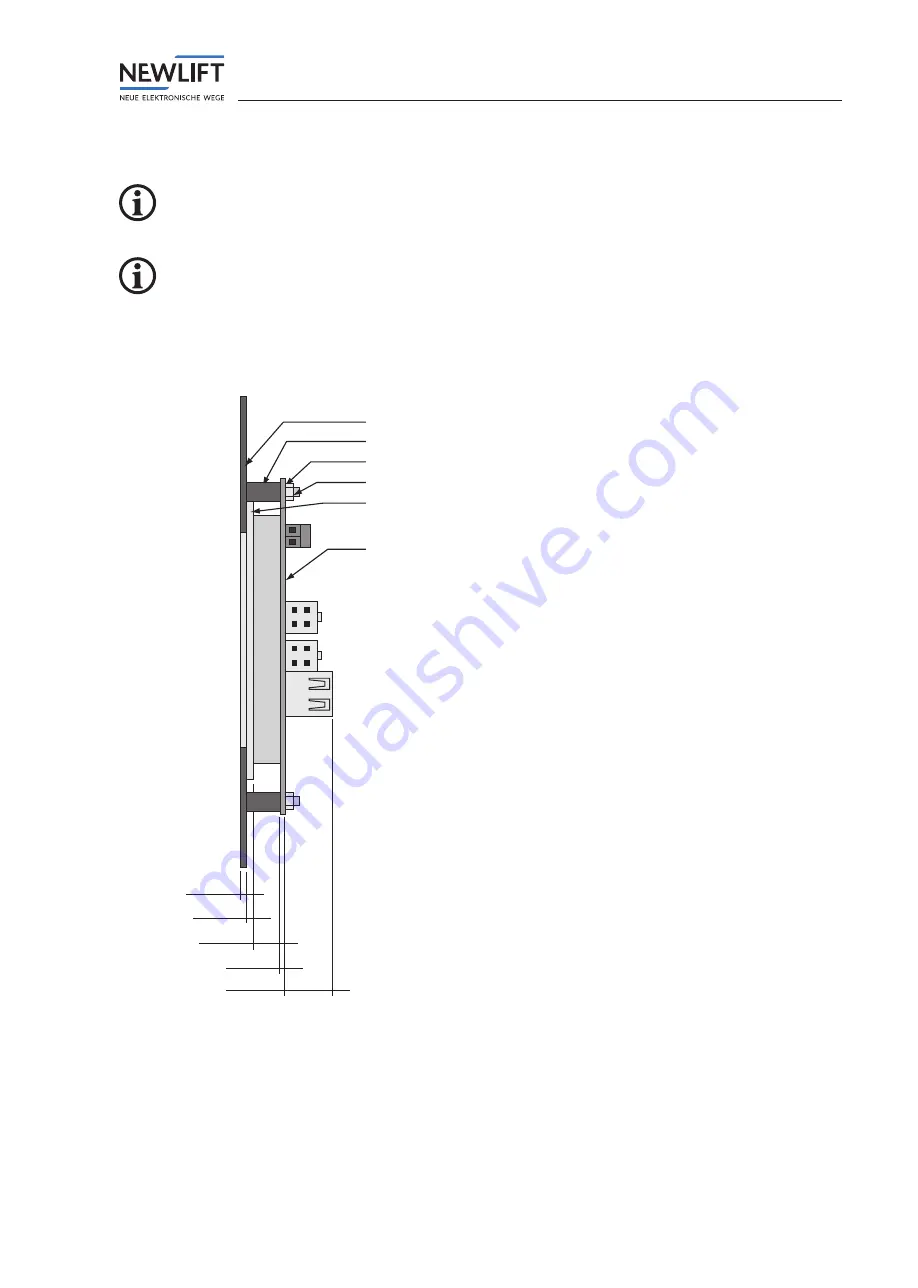
Side view
Panel
Spacer sleeve
Nut
Display screen
DMT-TFT.110
Installation depth: 30 mm
2,0 mm
2,0 mm
2,0 mm
8,5 mm
1,6 mm
14,9 mm
Threaded pin M3 x 16 mm in panel
Installation drawing – side view in installed state.
Summary of Contents for EAZ DMT-TFT.110
Page 1: ...Destination call terminal MANUAL DMT TFT 110...
Page 46: ...NOTES...
Page 47: ...NOTES...


