52
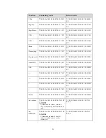
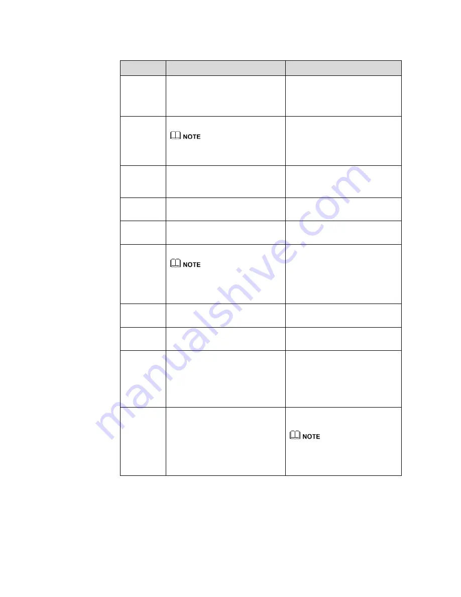
Function
Controlling codes
Return codes
Query the
firmware
version
number
7F 08 99 A2 B3 C4 02 FF 01 3D CF
7F 09 99 A2 B3 C4 02 FF 01 3D 01
CF
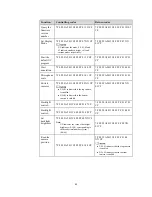
Set Display
Mode
7F 08 99 A2 B3 C4 02 FF 07 XX CF
XX indicates the mode. 00, 01, 02 and
03 indicate standard, bright, soft and
custom modes respectively.
7F 09 99 A2 B3 C4 02 FF 07 XX
01 CF
Start the
default UC
program
7F 08 99 A2 B3 C4 02 FF 01 3F CF
7F 09 99 A2 B3 C4 02 FF 01 3F 01
CF
Start
annotation
7F 08 99 A2 B3 C4 02 FF 01 40 CF
7F 09 99 A2 B3 C4 02 FF 01 40 01
CF
Microphone
mute
7F 08 99 A2 B3 C4 02 FF 01 41 CF
7F 09 99 A2 B3 C4 02 FF 01 41 01
CF
Switch
cameras
7F 08 99 A2 B3 C4 02 FF 08 XX CF
XX=01 indicates that the top camera
is enabled.
XX=02 indicates that the bottom
camera is enabled.
7F 09 99 A2 B3 C4 02 FF 08 XX
01 CF
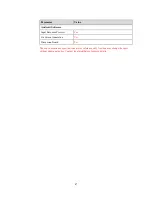
Backlight
c
7F 08 99 A2 B3 C4 02 FF 01 47 CF
7F 09 99 A2 B3 C4 02 FF 01 47 01
CF
Backlight
control -
7F 08 99 A2 B3 C4 02 FF 01 48 CF
7F 09 99 A2 B3 C4 02 FF 01 48 01
CF
Set
backlight
brightness
7F 08 99 A2 B3 C4 02 FF 09 XX CF
Note:
XX indicates the value of backlight
brightness (0-100), corresponding to
the hexadecimal number system
(00-64).
7F 09 99 A2 B3 C4 02 FF 09 XX
01 CF
Read the
camera
position
7F 08 99 A2 B3 C4 02 FF 01 44 CF
7F 09 99 A2 B3 C4 02 FF 01 44
XX CF
XX=01 indicates that the top camera
is enabled.
XX=02 indicates that the bottom
camera is enabled.
Summary of Contents for BNL16X5
Page 1: ...Collaboration Touch Screen User Manual Newline Interactive Inc www newline interactive com...
Page 10: ...9 1 3 Ports Front Ports...
Page 11: ...10 Rear Ports Front Buttons...
Page 15: ...14 2 Installation Guide 2 1 Safety Precautions Installation Environment...
Page 18: ...17...
Page 22: ...21 Step 4 Select in the Tablet PC Settings window...


