


5
A
A
B1
SCREW M3.5 X 35
1
1
3
3
2
2
4
4
B
B
B
B
B1
A1
A
A
SCREW M3.5 X 35
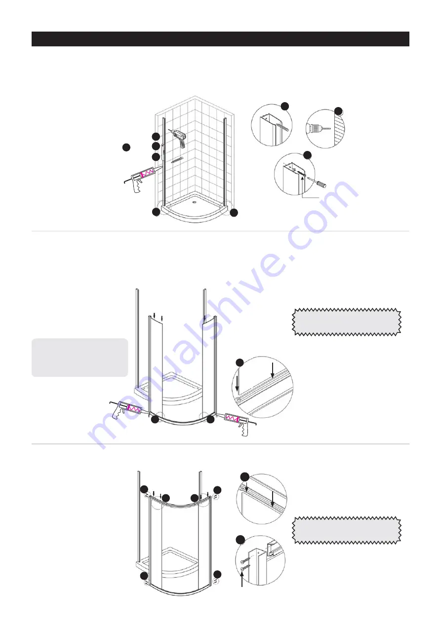
Note:
Use lubricant on screws that
fasten into top & bottom rails.
Note:
Apply a small bead of
silicone at joint as indicated prior
to fully fastening up. Clean off
excess.
1
2
3
4HYRV\[[OLWVZP[PVUPUNVM[OL^HSSWYVÄSLZYLMLY[V[OL3H`V\[7SHUVUWHNLMVYTLHZ\YLTLU[Z
Using a soft pencil or masking tape mark out the outside boundary line on the base and up the walls
with a spirit level. Use the wall channel holes to pre-drill a 2mm lead hole in the lining.
( ,UZ\YL[OLZWHJLYISVJRZHYLPUWVZP[PVUYLMLY[VHZZLTIS`KPHNYHTVUWHNLP[LT
) ;HRL[OLIV[[VTJ\Y]LKOVYPaVU[HSYHPSHUKPUZ[HSS[OL[^VÄ_LKWHULSZ56;,!;OLZJYL^OVSLZ
PU[OLÄ_LKWHULSWYVÄSLZHYLVMMZL[*OLJR[OH[[OLZLHSPNU^P[O[OLZJYL^SVJH[PVUZPU[OLJ\Y]LK
OVYPaVU[HSYHPSZ0M[OL`KVUV[SPUL\WJOHUNLV]LY[OLÄ_LKWHULSZ<ZL_MYHTLZJYL^Z
Add the top horizontal rail using the M3.5 x 35 screws fasten this frame together.
INSTALLATION
7YPVY[V^HSSJOHUULSÄ_PUN
Apply a continuous 7mm bead
of silicone on back of channel
plus short bead across tray to
liner join at base of channel.
A
B
B
C
C
D
D
A
A
IMPORTANT:
Complete all items in 2
& 3 before intalling to wall channels


