P.O. Box 1306, Newport Beach, California 92663 • Phone: 714-751-0488 • Fax: 714-957-1621 • E-Mail: techservice@newmarpower.com
www.newmartelecom.com
2
I) Overview
The Centurion Rectifier System comprises a low profile 3.5" (2 RU)
shelf which accommodates up to three 550 watt, -48 or +24 volt hot-
swap rectifiers and a system controller/monitor module. The system
is scalable/adaptable for N, N+1 or N+2 configurations.
Front panel test points and single point voltage adjustment pot are
provided for fine-tuning output to the requirements of sensitive loads
or float charge requirements.
Alarm contacts enable remote alarms for the rectifier system.
Front panel OK/FAIL LED's allow monitoring status of each rectifier
individually.
The Centurion system is engineered for compatibility with
NEWMAR’s Power Function Manager (PFM 400) and circuit breaker
distribution panel (DST 20/10). See section VIII, optional system
components.
II) Shelf Installation
A) Mounting
Two sets of mounting ears are provided for 19" and 23" rack
mounting. Ear attachments are in the 6” forward mounting position
and at the four corners for four point cabinet mounting (contact
Newmar for additional mounting ears.) Use the six #6-32 x 1/4" pan
head mounting screws and lock washers to secure the ears.
Note: Flush mounting is only recommended with rear support or
four point cabinet mounting.
The Centurion Rectifiers are front-to-back forced-air cooled,
therefore no empty rack positions are necessary either above
or below the unit to maintain proper operating temperature.
Other rack components may be installed above or below rectifier
shelf. Maintain at least 6" in front of and behind shelf to allow air
circulation.
B) AC Input
The Centurion Shelf/Rectifiers operates from 90-264 VAC, 47-63
Hz input. The rectifier shelf is designed for hard wiring however a
power cord can be fitted to the shelf if desired.
AC Input Wiring Chart:
Input
Recommended
Recommended
AC Input
AC Input
Wire Size
Circuit Size
115VAC
12AWG
25Amp
230VAC
14AWG
15Amp
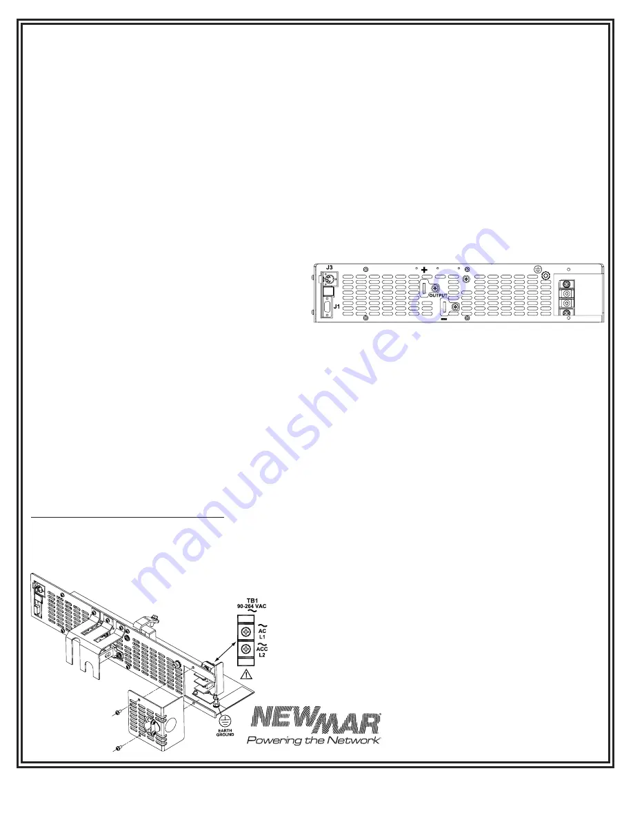
To access the AC wiring compartment, loosen the two screws
securing the compartment cover as shown figure 1:
AC Wiring Compartment
Two AC cable entry points are provided. Feed the AC cable thru
the strain relief and then attach AC wires to the input terminal
block (TB1) as shown in figure 1. For line to neutral sources, connect
Hot/Line to “AC/L1” & Neutral to “ACC/L2”. A chassis mounted 10-
32 stud is provided for earth grounding.
CAUTION (230V AC applications only): 230V AC sources should be
protected by a double pole circuit breaker.
After wiring is completed securely tighten the two cable strain relief
screws and secure cable entry screws.
C) DC Output/Battery Connection Points
Note: Refer to the CRS Rear Panel Diagram, figure 2 below for
wiring DC output.
Minimum Output Wire Size
24 Volt (60 Amps) 6 AWG • 48 Volt (30 Amps) 10 AWG
Centurion Shelf Rear Panel Diagram
III) Rectifier Installation/Operation
A) Installation
The Centurion Shelf is voltage specific, 24 or 48 volt and accepts
either model CR 48-10 (-48 VDC) or CR 24-20 (+24 VDC) Rectifier
Modules respectively. The modules are keyed so that a 24V module
cannot be inserted into a 48V shelf, and visa versa. The system is
designed for module installation while the shelf is "hot", therefore the
modules may be removed or inserted while AC is being applied to
the shelf and loads are being powered. CAUTION: Ensure that the
power switch on the front panel of the rectifier is in the OFF position
prior to inserting or removing the module.
Slide the rectifier into the open RECTIFIER A position and secure it
using the front panel captive retaining screws. Two blank panels for
covering unused bays are factory installed in the RECTIFIER B and C
positions and are easily removed for installing additional rectifiers
These should be left in place in any unused bay(s) to optimize
proper air flow from the fans through the shelf.
B) Rectifier Module Output Indications
This indicator will glow green whenever the rectifier module is
producing normal operating voltage. In the event of failure or the
inserted power module’s power switch is in the off position, the LED
will glow orange.
IV) Shelf Controller & Rectifier Operation/Adjustment
A) Start-up
1) Apply recommended AC voltage to the shelf AC input terminal
block.
2) Turn the on/off power switch located on each installed rectifier to
the on position.
3) Verify each installed rectifier’s “Output Power”
LED is illuminated green.
4) Verify the “Output OK” green LED on the
controller is illuminated.
AC Wiring
Compartment
Figure 1
Figure 2


